Drone Prop Dyno
Propeller Dynamometer
This is a test stand for small drone motors and propellers. You bolt a motor, prop, and ESC to it, run one command on the PC, and it ramps the throttle from idle to wide open while measuring thrust and current draw at every step. It outputs thrust vs current curves, thrust vs pwm, and current vs pwm. This way I can qualitatively analyze motor/prop performance in cases where manufacturers don't provide this data or it's a non-standard prop/motor combo. This data is used to determine whether or not a motor and prop are suitable for a given drone design. Also allows me to plan a drone build around known thrust characteristics from the start.
Demo Video
The dyno running a full sweep, from the hardware walkthrough to the finished plots.
The Test Stand
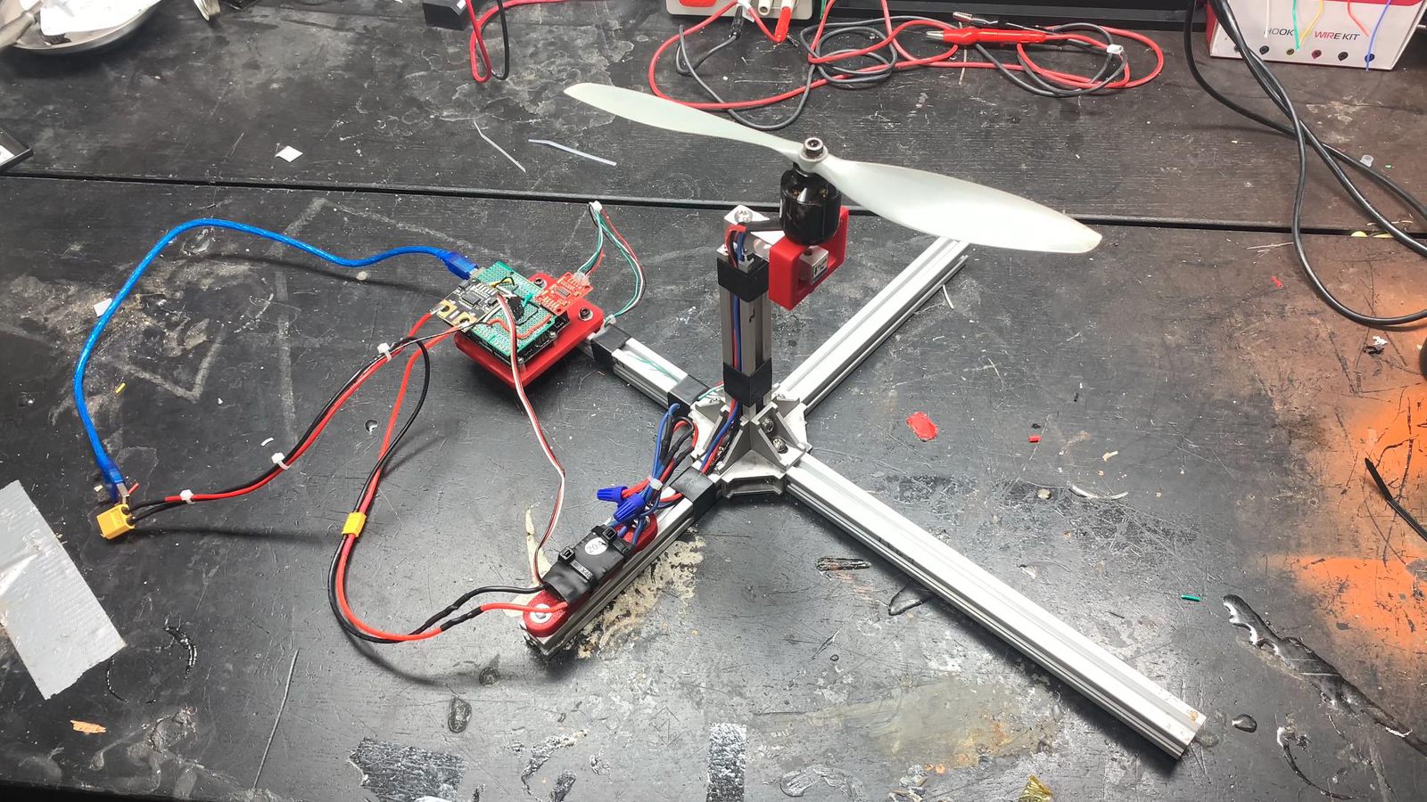
The whole rig. The base is a cross of aluminum extrusion with a vertical mast, and a load cell cantilevered off the top of the mast. The motor bolts to a 3D printed adapter on the free end of the load cell, so all the thrust it makes pushes straight down on the beam. This requires mounting the prop upside down and slightly affects the performance due to the high pressure zone/ground effect, but this configuration prevents accidental takeoffs due to the thrust often being more than this rig weighs. A sideways thrust configuration would likely be more representative of real flight performance, but this upward thrust setup is much safer. It'll tend to overestimate current draw because air doesn't flow past the prop as unrestricted as a sideways setup would be. The ESC sits in a printed cradle on one arm of the base and the Arduino lives in a printed tray next to it. Everything is bolted to extrusions so I can move things around easily. Different motor mounts can be easily printed to test motors of different bolt patterns.
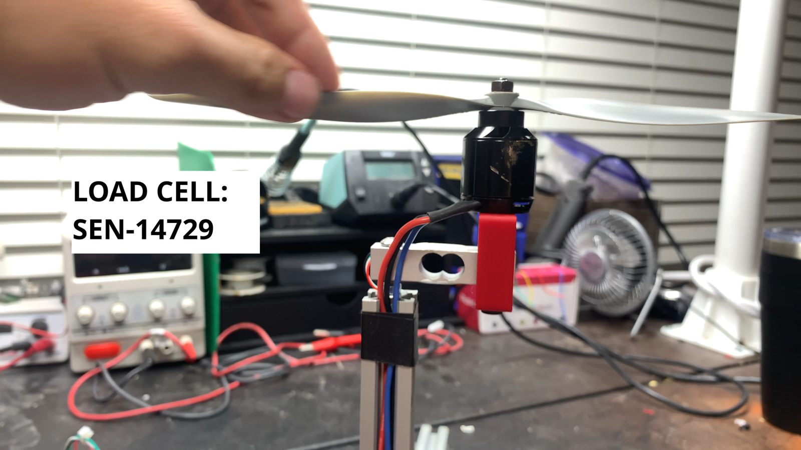
The load cell is a 5kg TAL220B (SparkFun SEN-14729) — a strain gauge Wheatstone bridge in an aluminum bar. The bar only flexes a few thousandths of an inch under thrust, so it doesn't move the motor around while it's running. I calibrated it against a 5 lb reference weight, which is where the calibration factor in the firmware comes from.
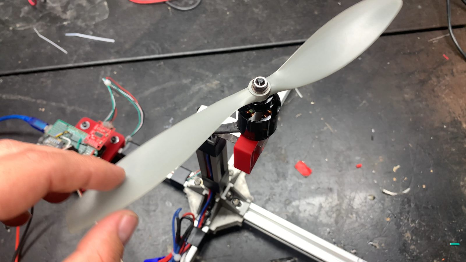
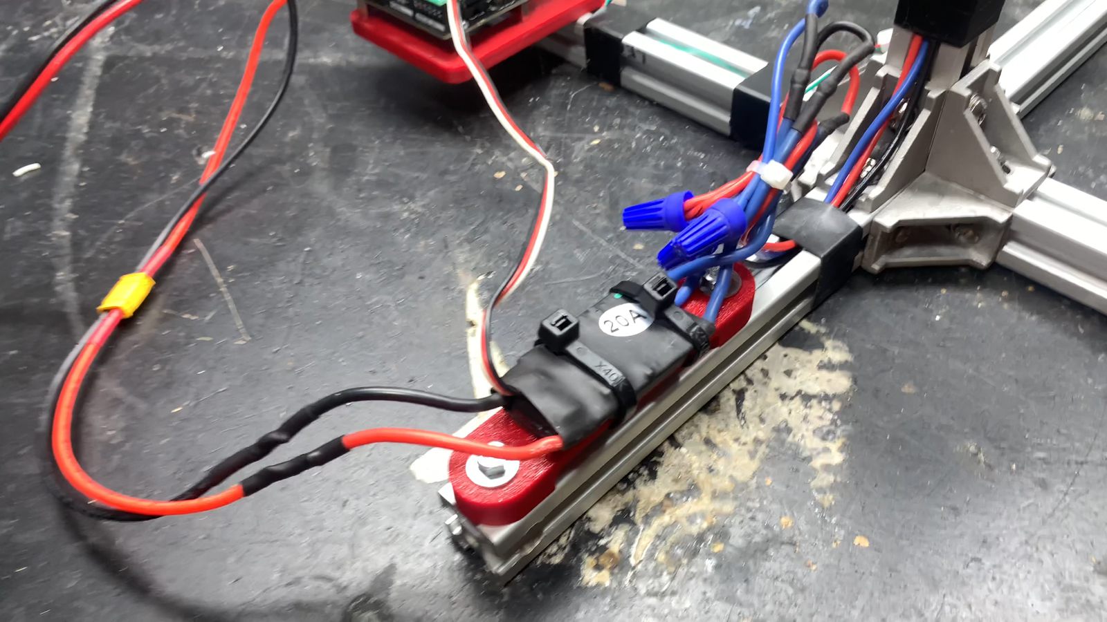
The motor screws onto a 3D printed adapter clamped to the free end of the load cell. The 20A ESC is zip tied into its own printed cradle down on the base, away from the prop wash so nothing gets pulled up into the blades.
Electronics
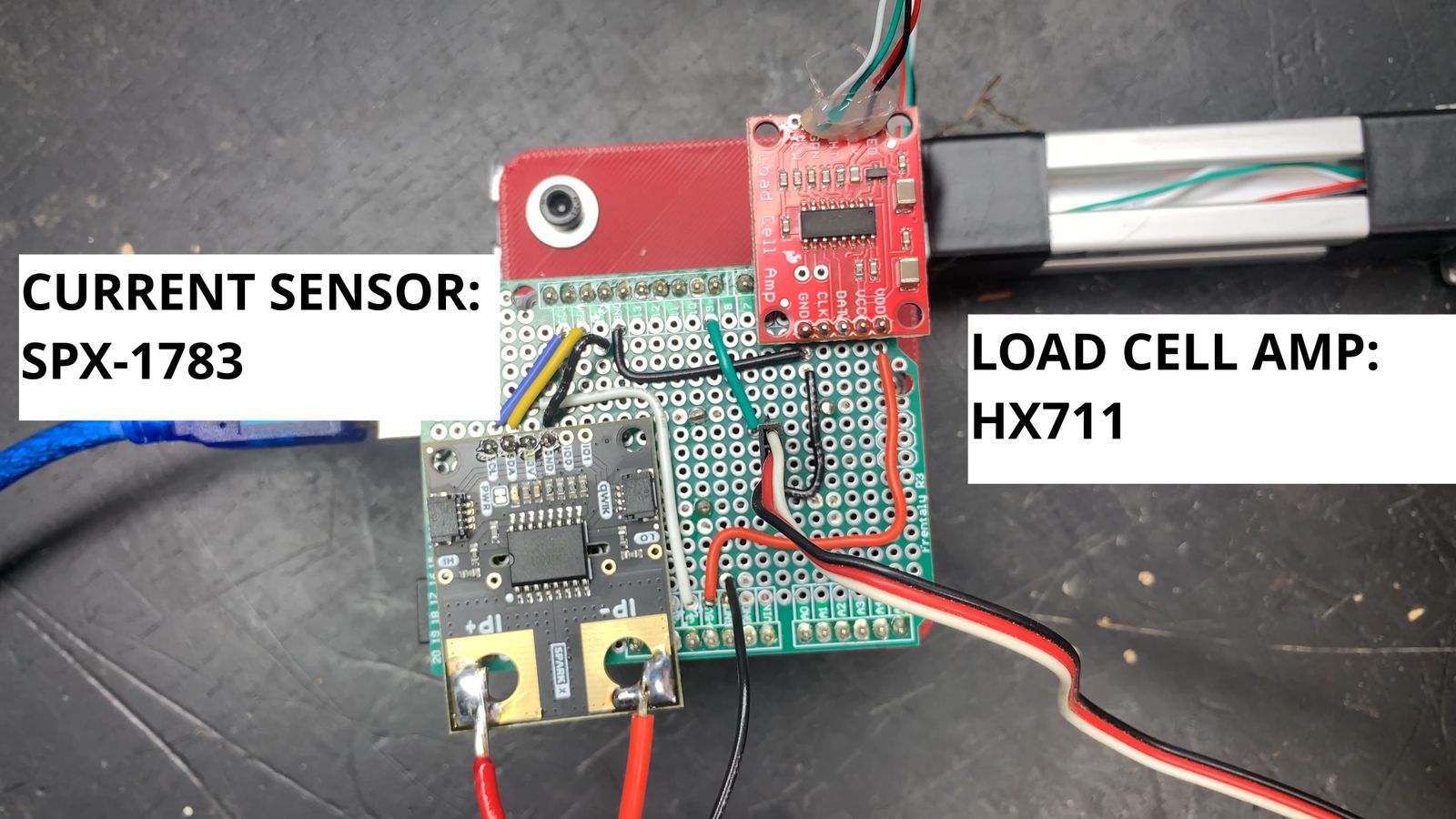
An Arduino Uno with a solderable proto shield carries the two sensors. The HX711 is a 24 bit ADC that reads the load cell over a two wire interface, and the ACS37800 Qwiic power meter (SparkFun SPX-17873) measures voltage and current over I²C. The power meter goes inline on the positive lead feeding the ESC, so it sees exactly what the motor is pulling and nothing else.
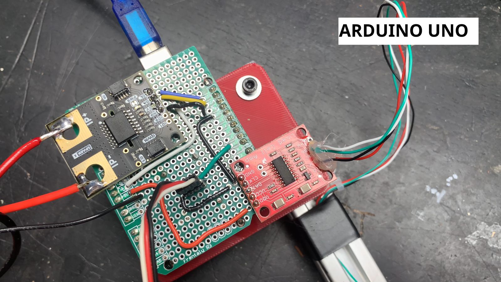
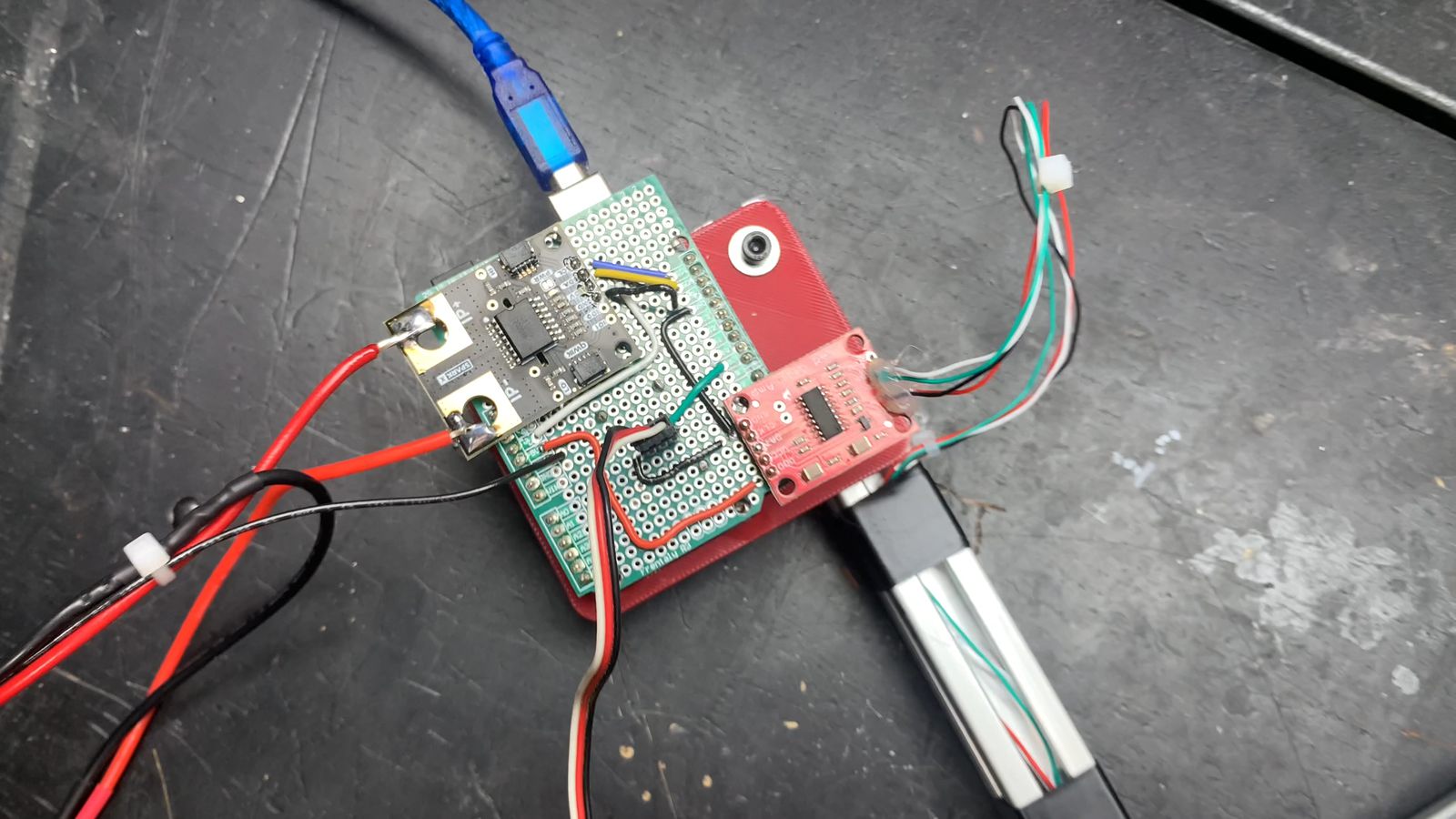
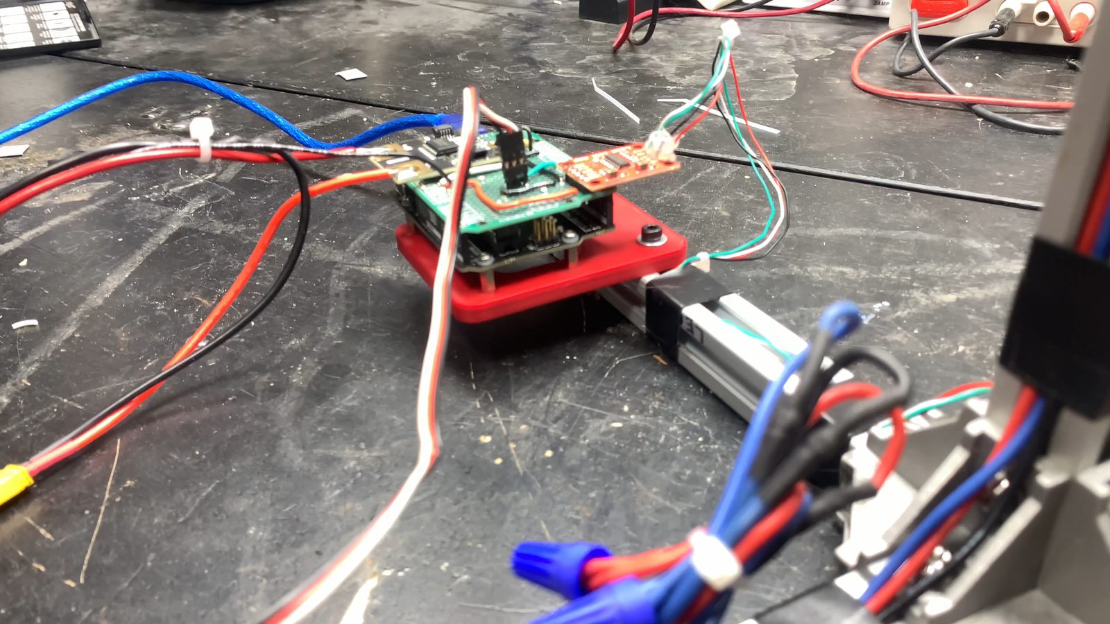
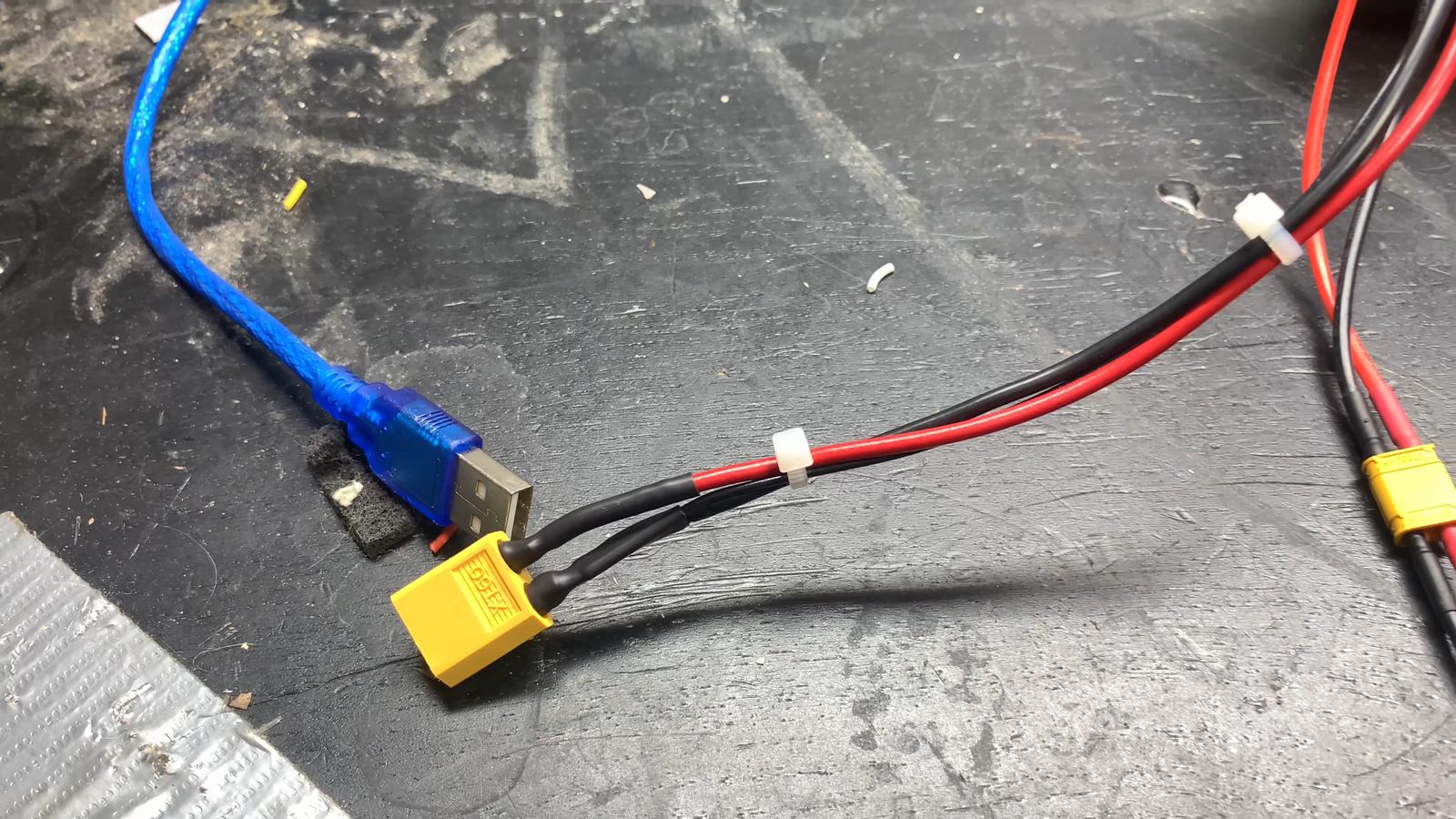
The Uno also generates the ESC's PWM signal on pin 9 and talks to the PC over USB, which is the only thing that USB cable is doing — motor power comes off a separate 3S lipo through an XT60. All the printed parts (motor adapter, ESC cradle, Arduino tray) are in the github repo along with the firmware and the host app.
Running a Test
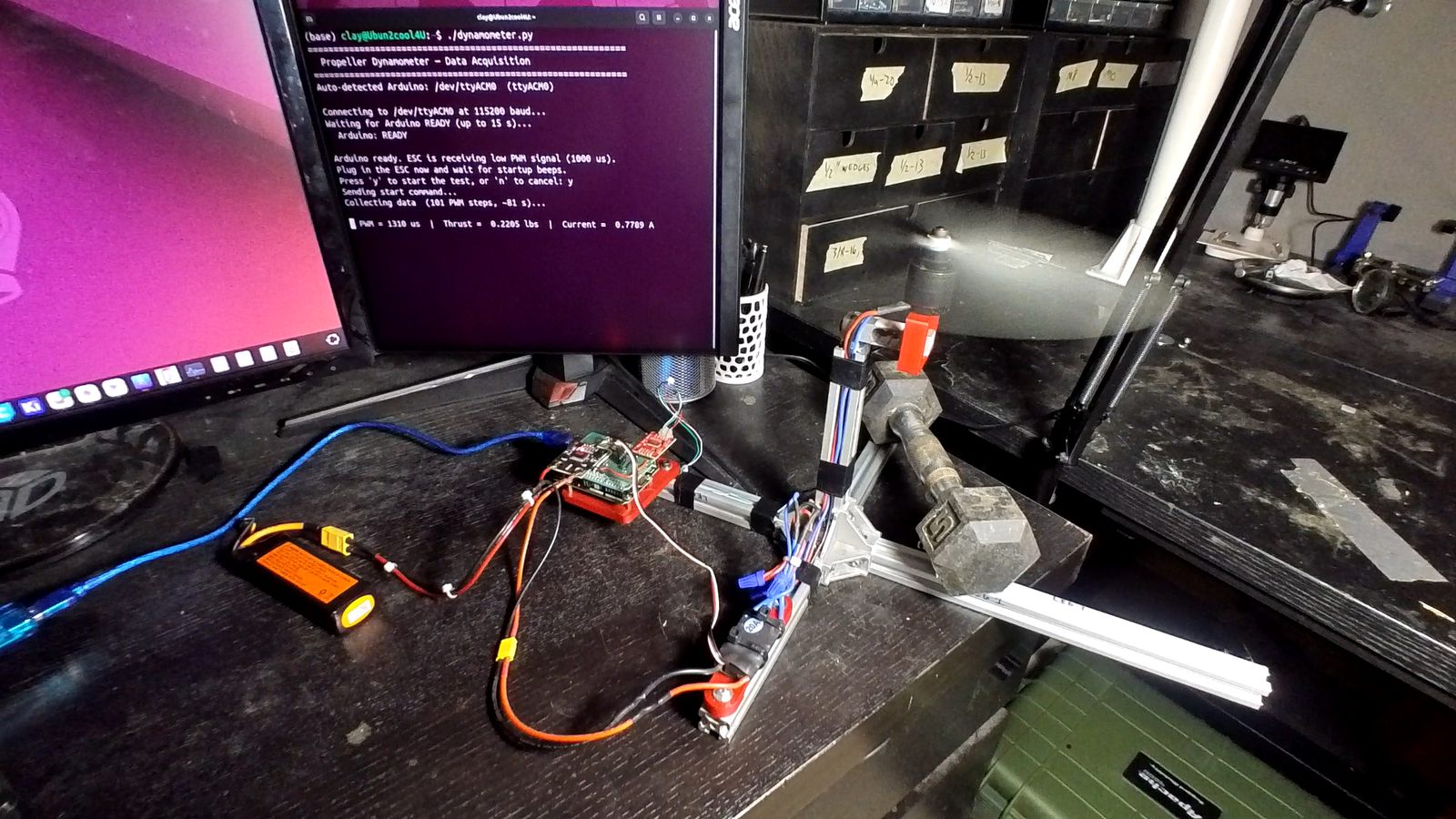
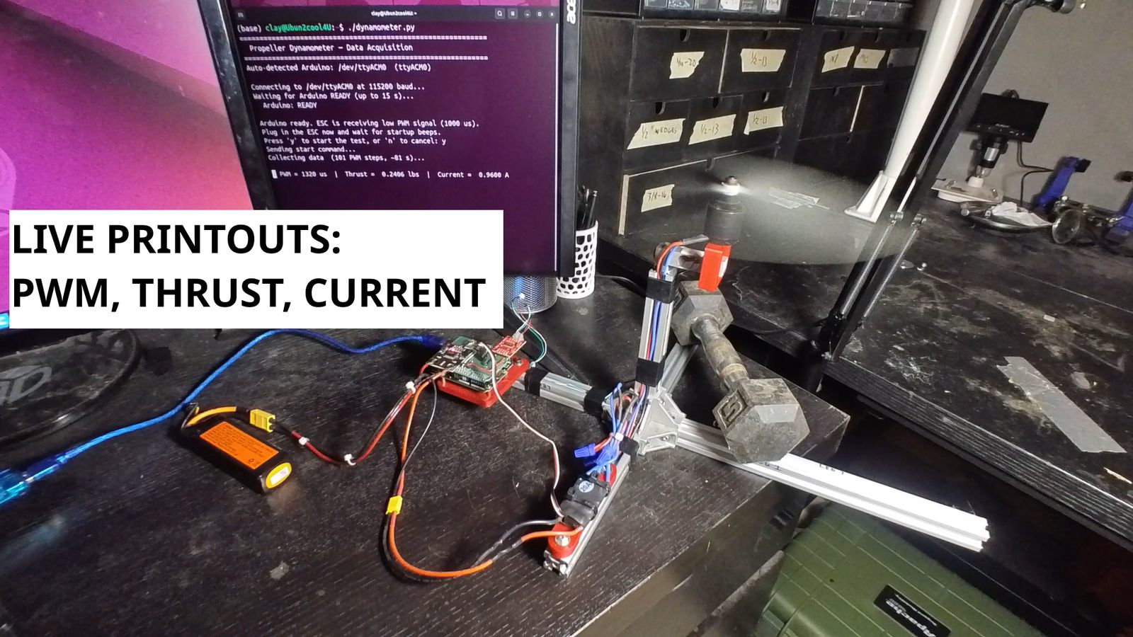
Running a sweep. The python app on the PC auto-detects the Arduino, waits for it to arm the ESC at 1000 µs, and then prompts me to plug in the motor power and listen for the arming beeps. After that it sends a start command and the firmware walks the throttle from 1000 to 2000 µs in 10 µs steps, holding each step for half a second while it reads thrust and current. That's 101 data points and about 81 seconds of run time. Every reading gets printed live so I can watch it climb, and at the end the app writes a timestamped CSV and generates the plots automatically. The weight is there for safety to keep the stand from walking across the bench under vibration. It's self supporting and won't tip over unless something goes horribly wrong.
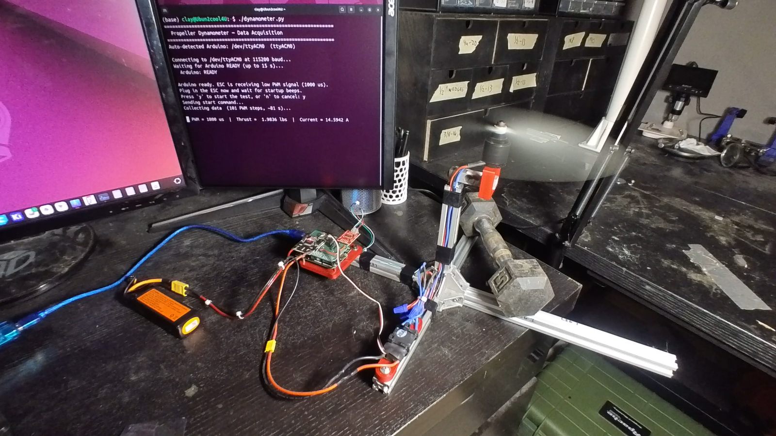
Near the top of the sweep: 1800 µs of throttle command, 1.98 lbs of thrust, 14.6 Amps. Watching those three numbers together is the whole point of the machine.
Results
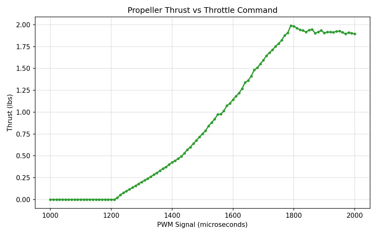
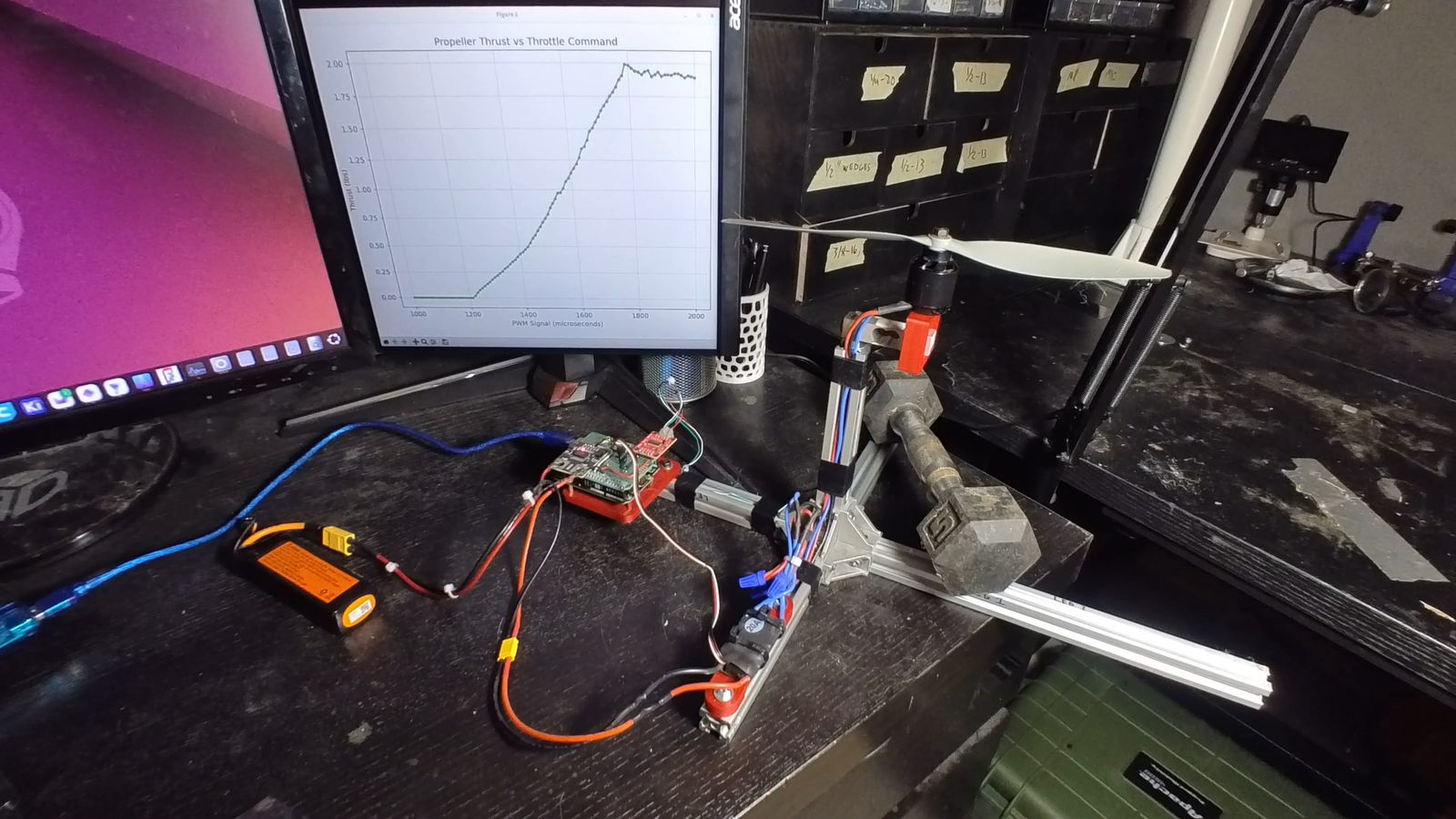
Thrust vs throttle command for one of the salvaged motors turning a 10" prop on 3S. Nothing happens at all below about 1210 µs, then it climbs almost linearly to just under 2 lbs at around 1790 µs. Past that it flattens out and even drops off slightly, which I think is the pack sagging as the test goes on rather than the motor doing anything interesting. This old salvaged ESC has an unusual PWM range of 1200-1800µs. The software is ESC agnostic, sweeping across the whole common range of 1000-2000µs. It's connectorized on one end and twist nutted on the other, so I can easily swap a different ESC in or change it's direction by swapping two wires. Code and plot generation works the same.
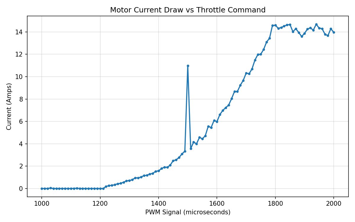
Current draw over the same sweep, peaking around 14.6 A. The single spike at 1500 µs is a bad reading from the power meter, not something the motor did — it's one sample sitting at 11 A with 3.4 A on either side of it. It only shows up once in 101 points so I left it in rather than quietly cleaning up my own data, but throwing a median filter across a few reads per step would get rid of it.
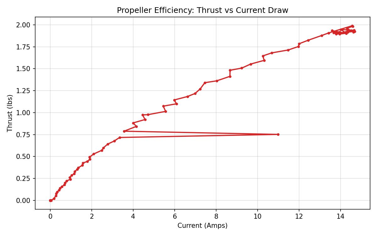
The one I actually care about: thrust against current draw. This is the curve that tells you what a given amount of battery buys you. It's steep down low and flattens out as it goes, so the last half pound of thrust costs about as much current as the first pound and a half. That bad sample from the previous plot is the horizontal spur hanging off the middle of the line.
I fed this curve straight into the endurance optimizer for my hex drone. Six of these motors makes around 12 lbs of static thrust, which set the weight budget for the whole airframe, and the thrust vs current relationship is what let me predict flight time for a bunch of different battery capacities and weights before I'd bought any of them. There's more about that analysis on my hex drone page. Next I'd like to run the same test at different voltages and with a few different prop sizes and pitches, since right now I only have one curve for one combination.