CNC Routing Bathymetry From Autonomous Boat
Pond Carving
I mapped this lake with my autonomous solar powered depth plotting boat called Gumption Trap II. Check my other pages about building it to see how it works. This video shows my process for generating a 3D woodcarving with a cnc router based on sonar data collected during the bathymetry survey. I also collected some data to improve the boat's control system.
Process Video
This quick video shows start to finish how I made the depth plot. It includes the boat operating and some analysis/processing of the data.
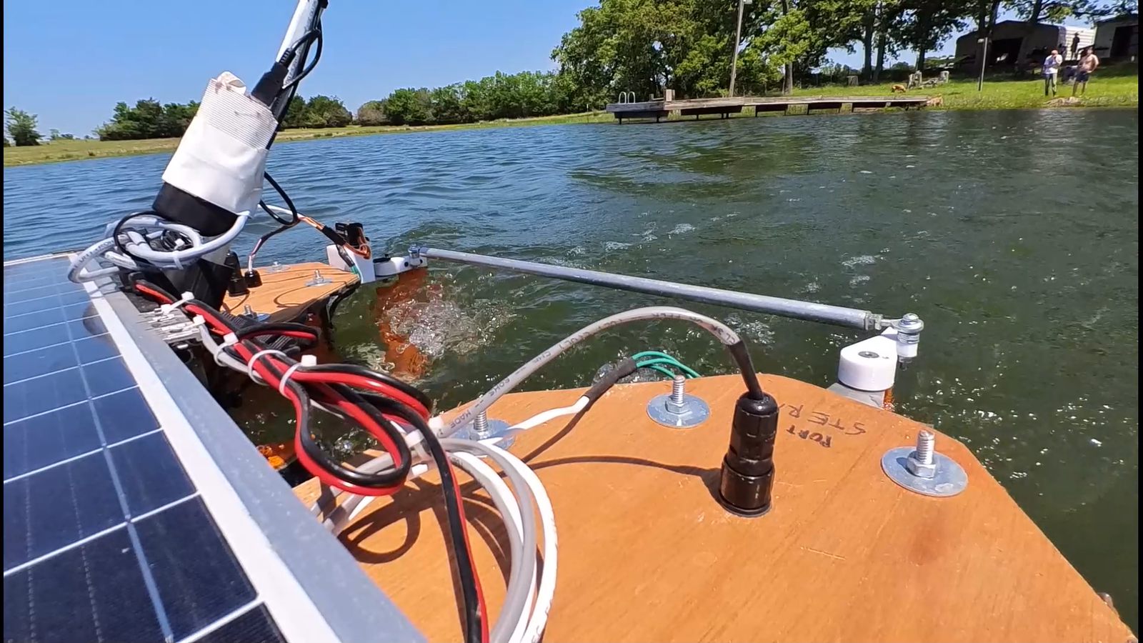
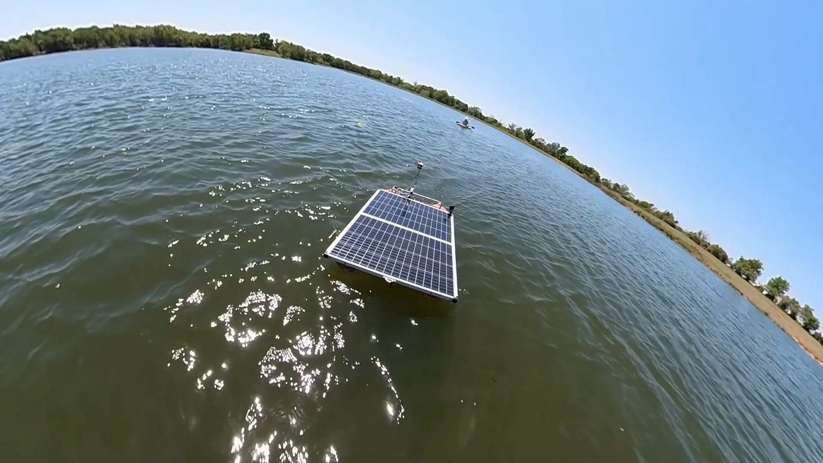
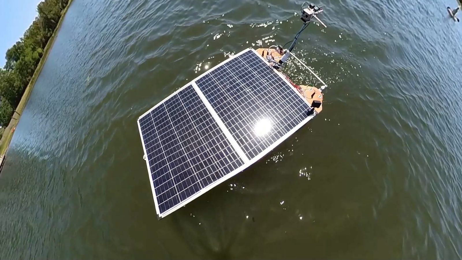
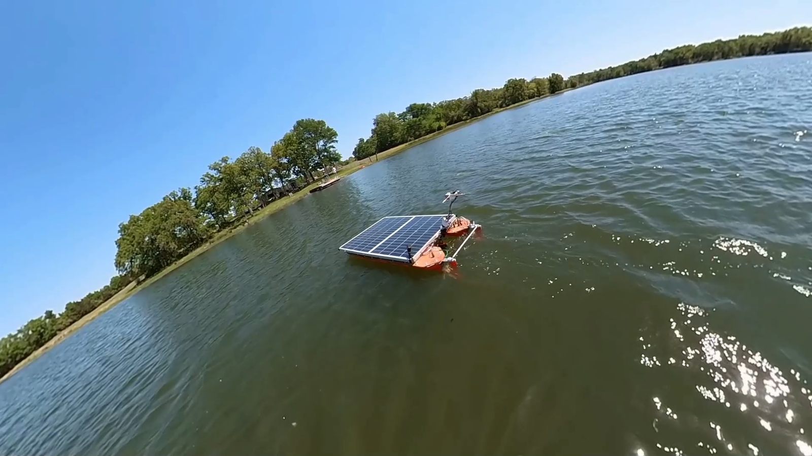
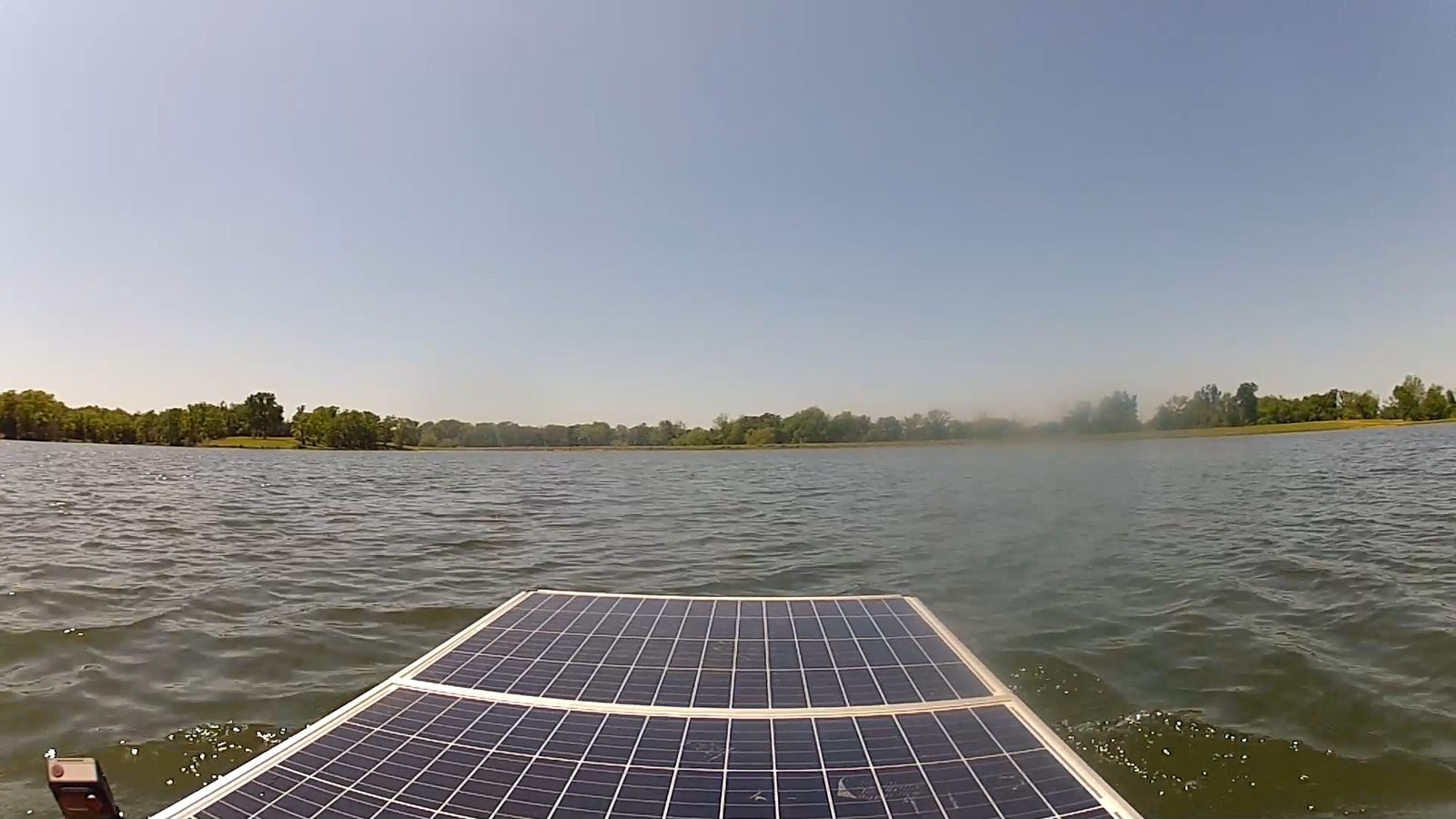
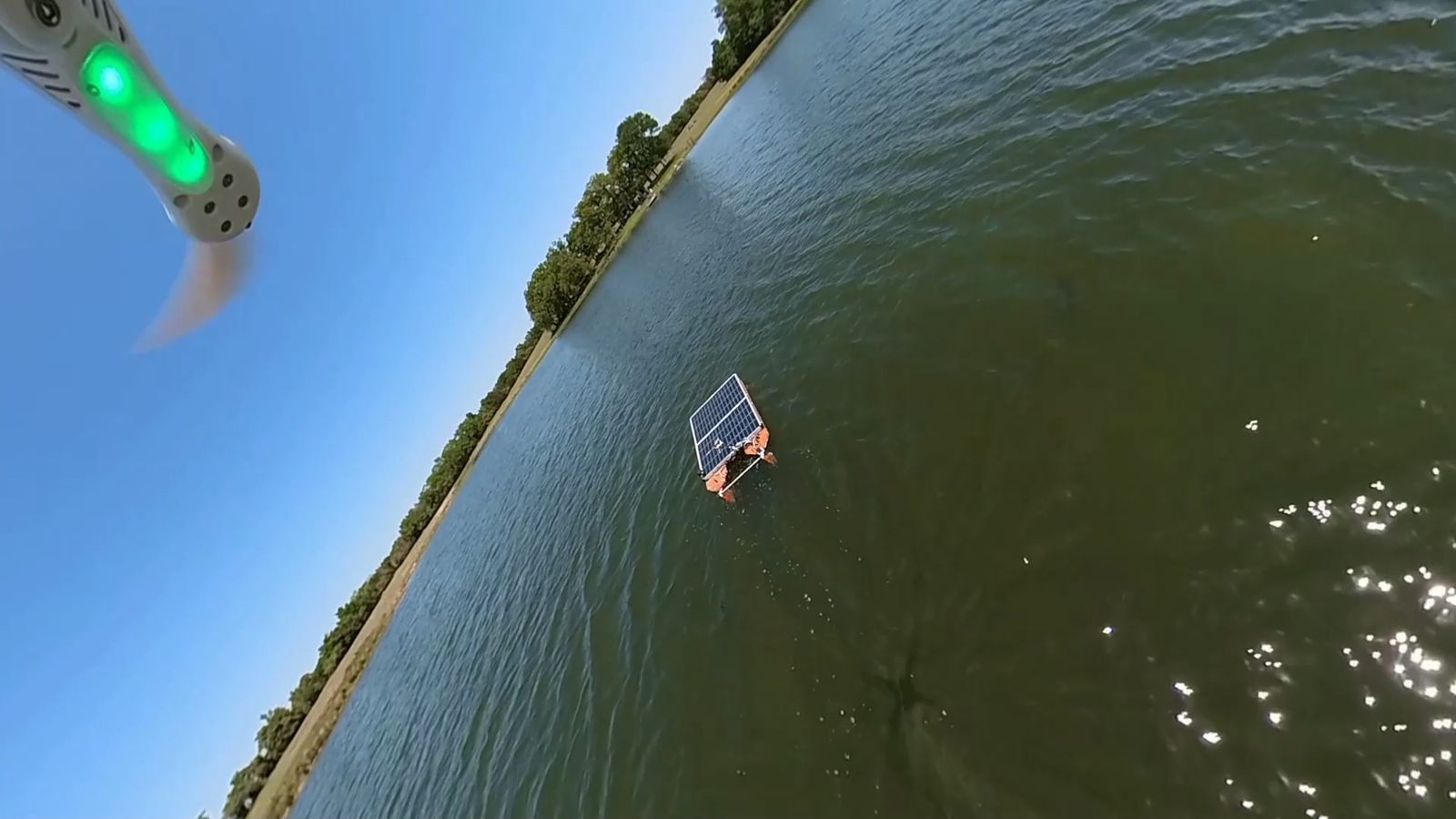
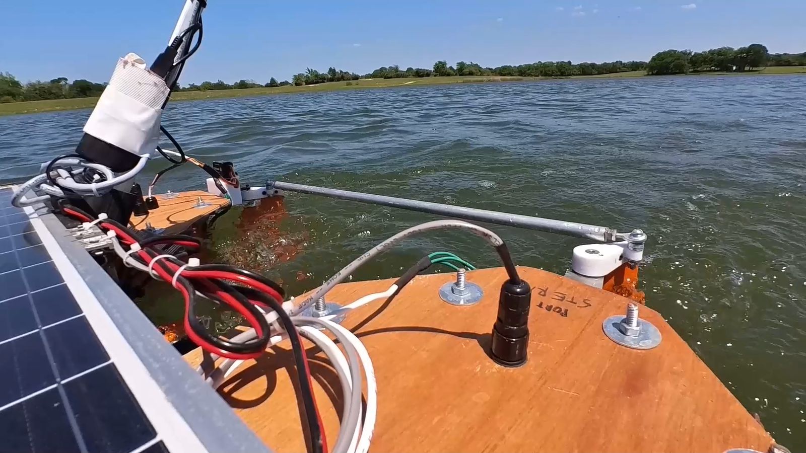
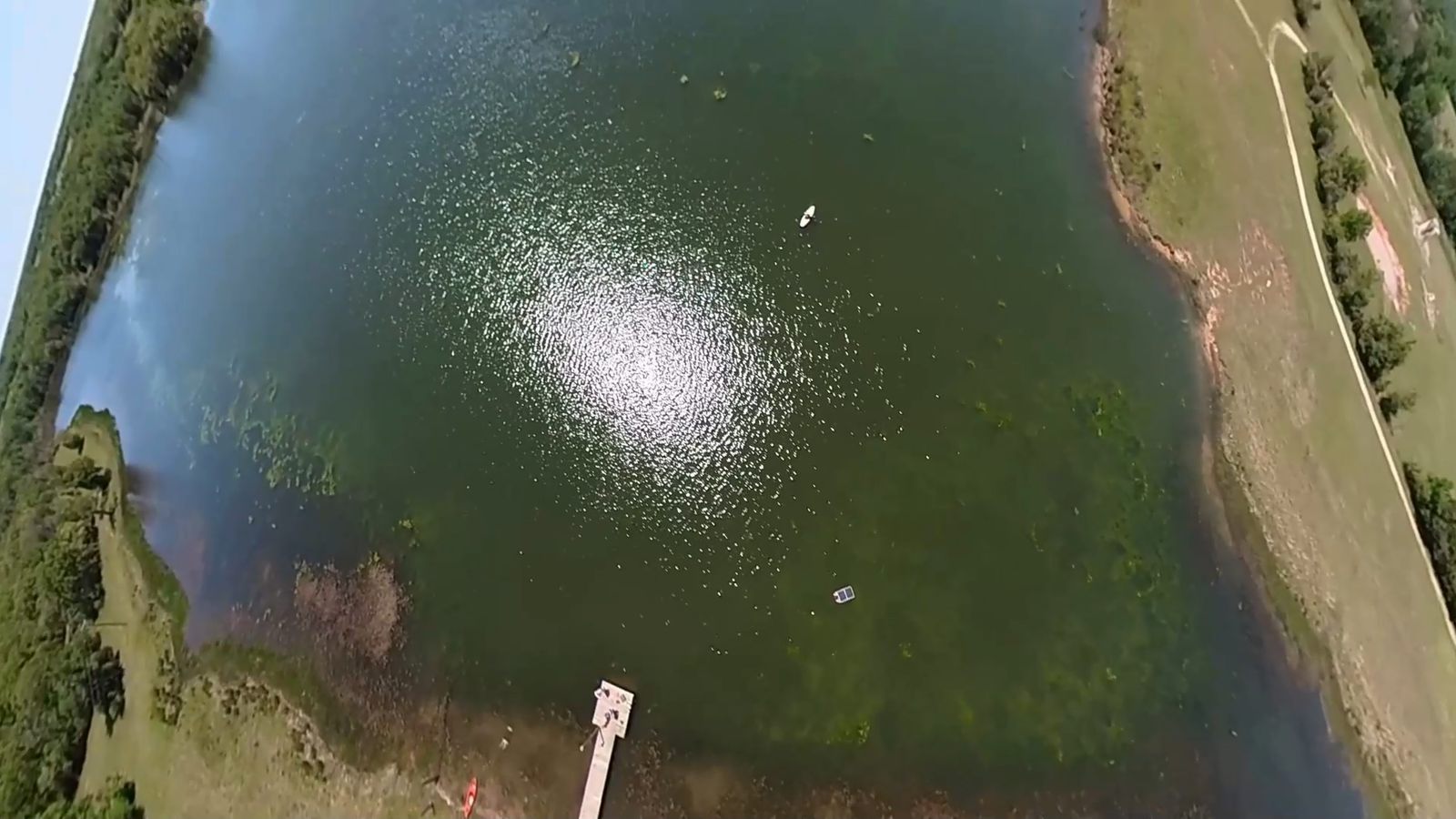
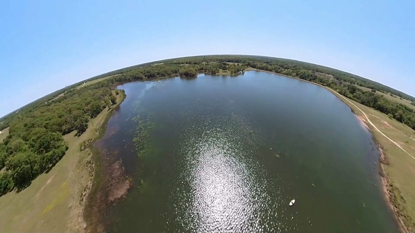
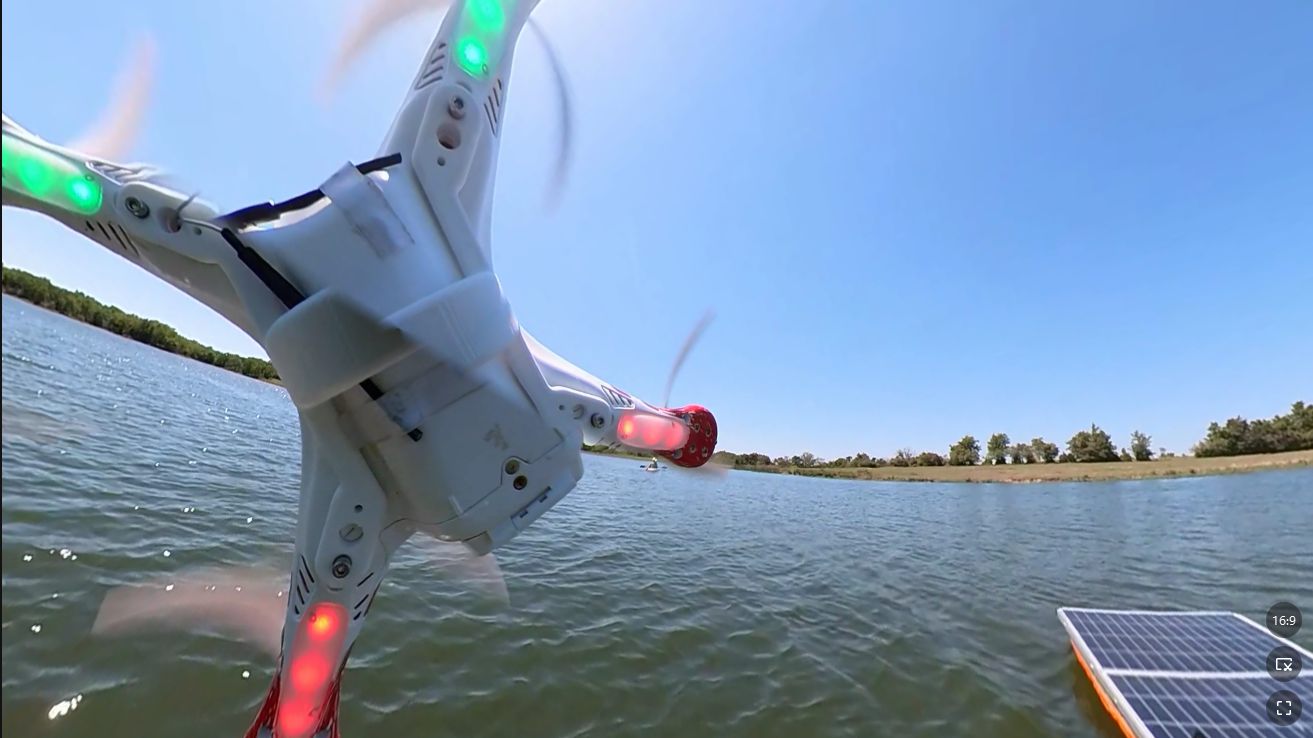
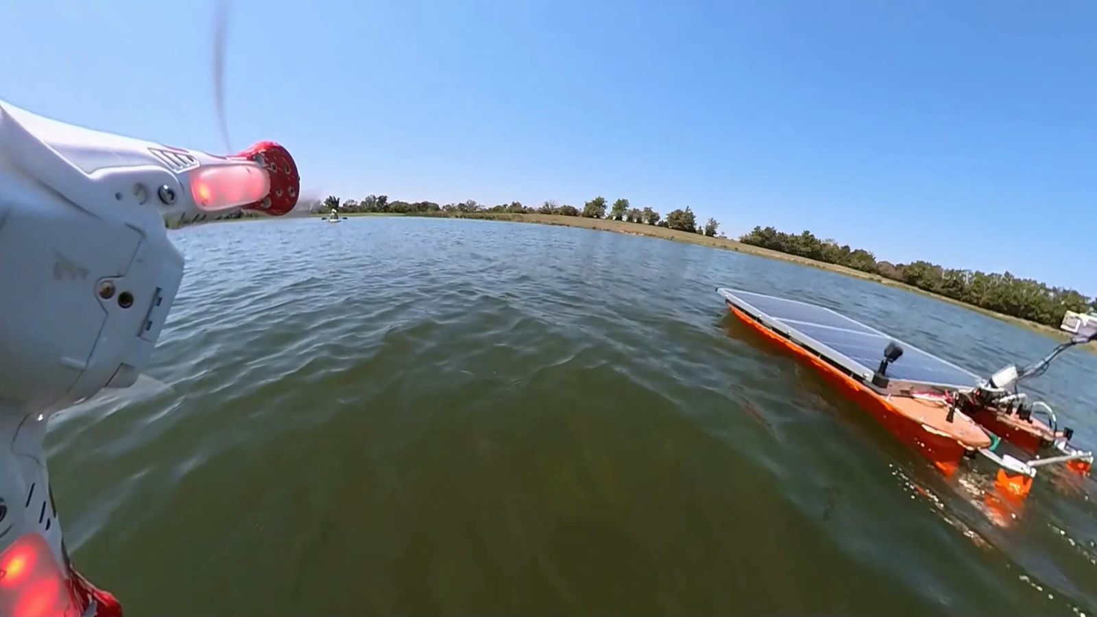
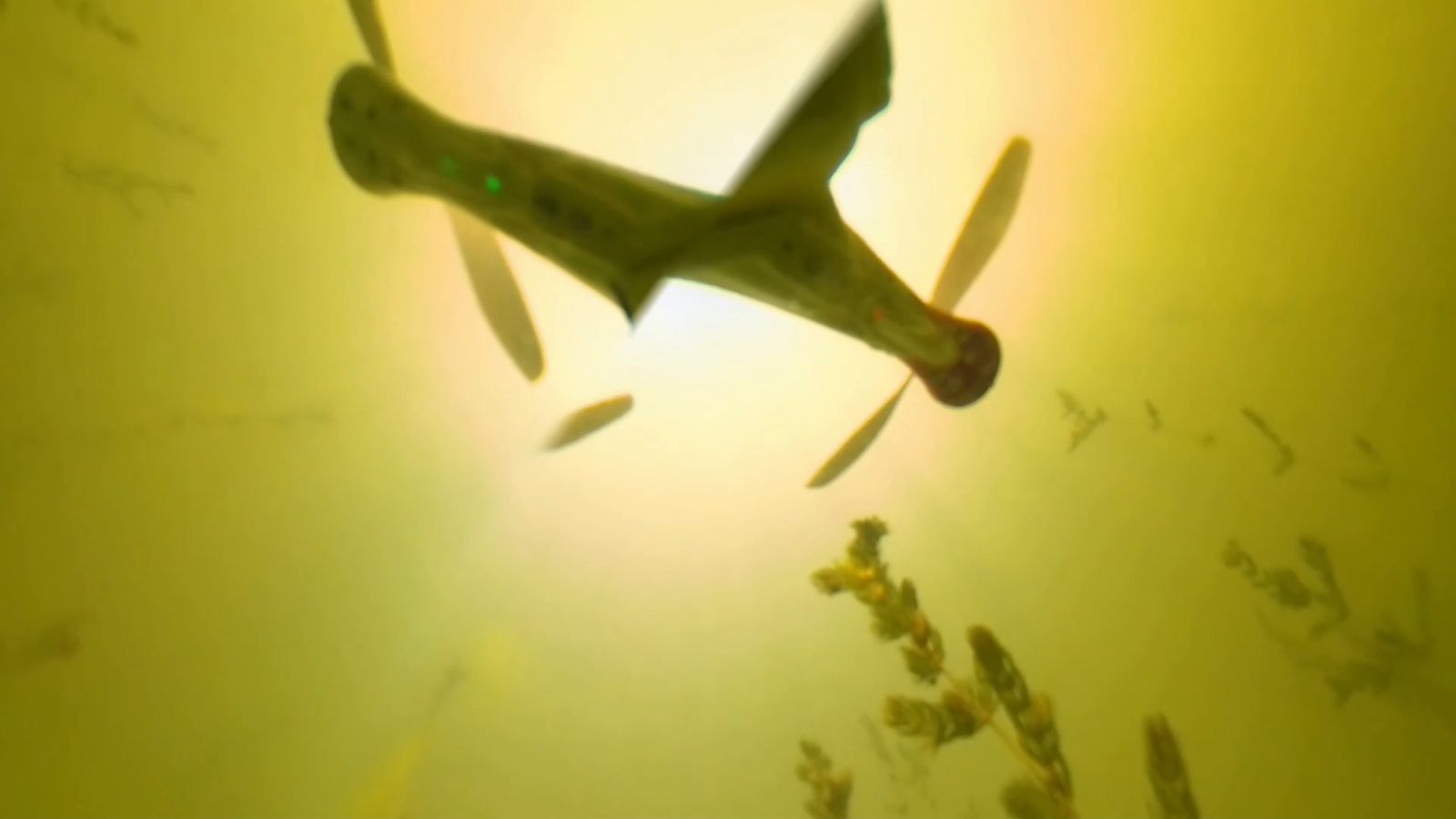
Some action shots from the bathymetry mission
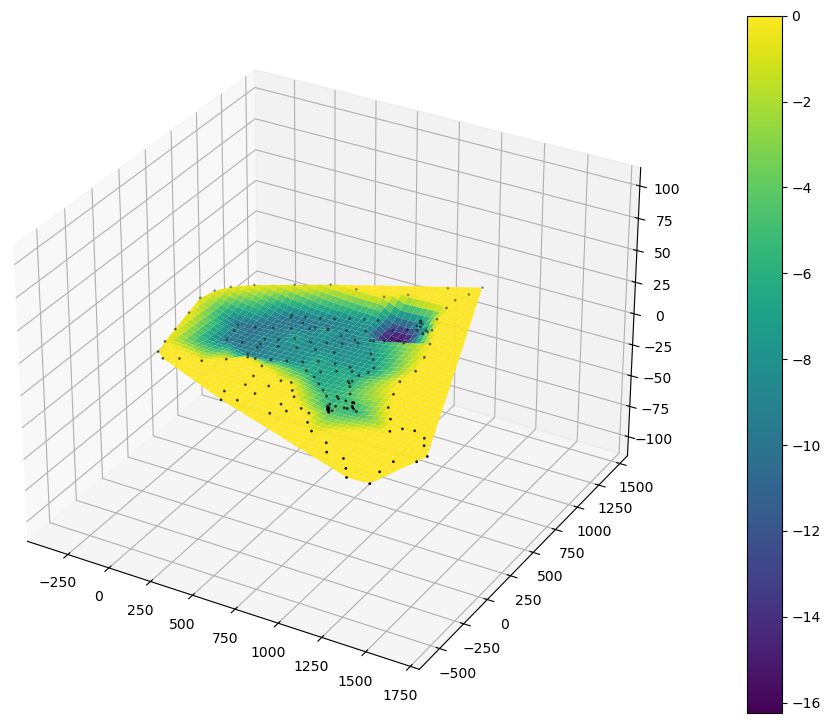
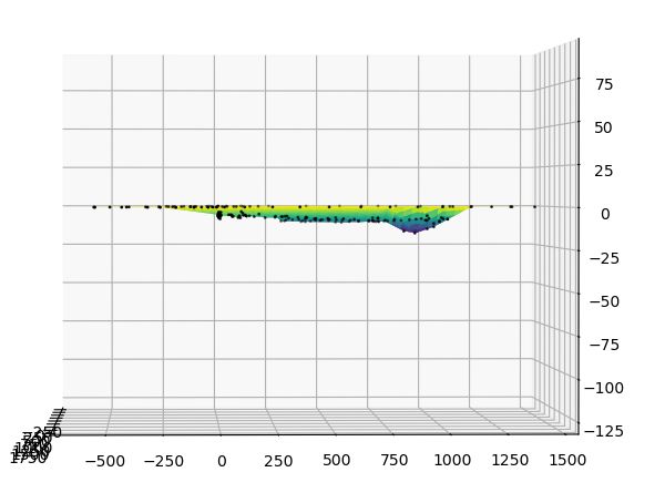
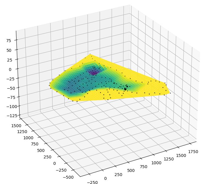
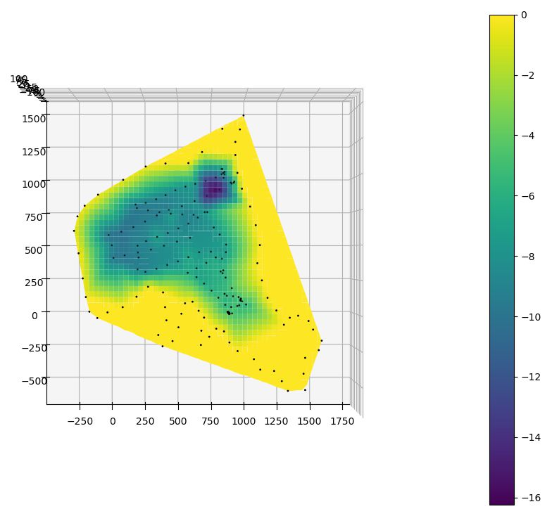
These are the raw depth maps I collected. All 3 axis in feet. It records GPS latitude and longitude but I only display it in feet to protect the privacy of this location on private property.
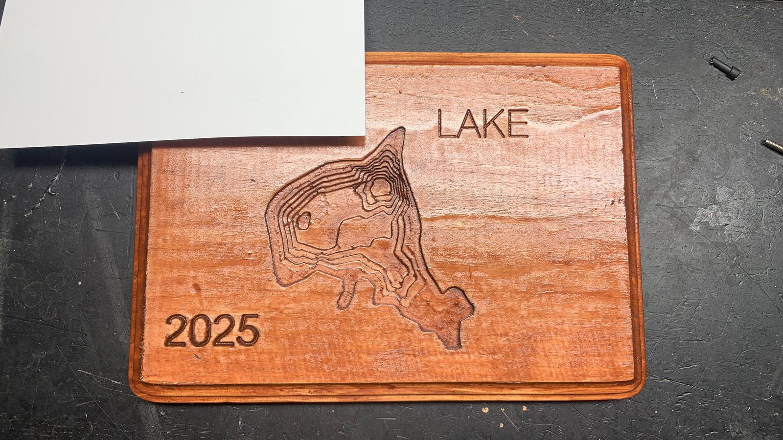
The final product, carved wood.
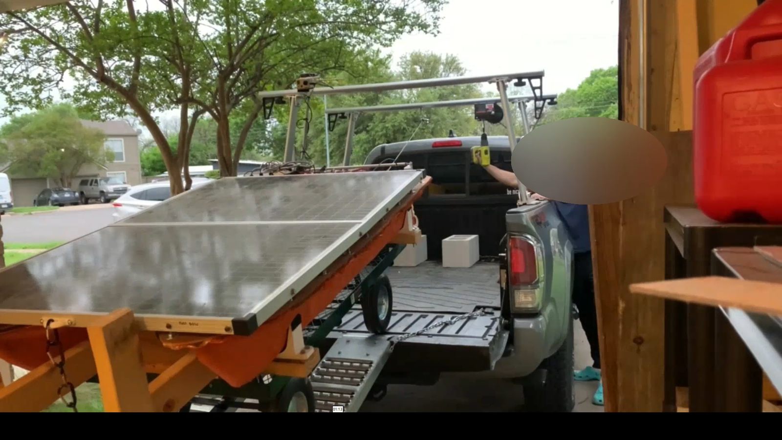
The winch system and wagon for getting the boat up into my truck.
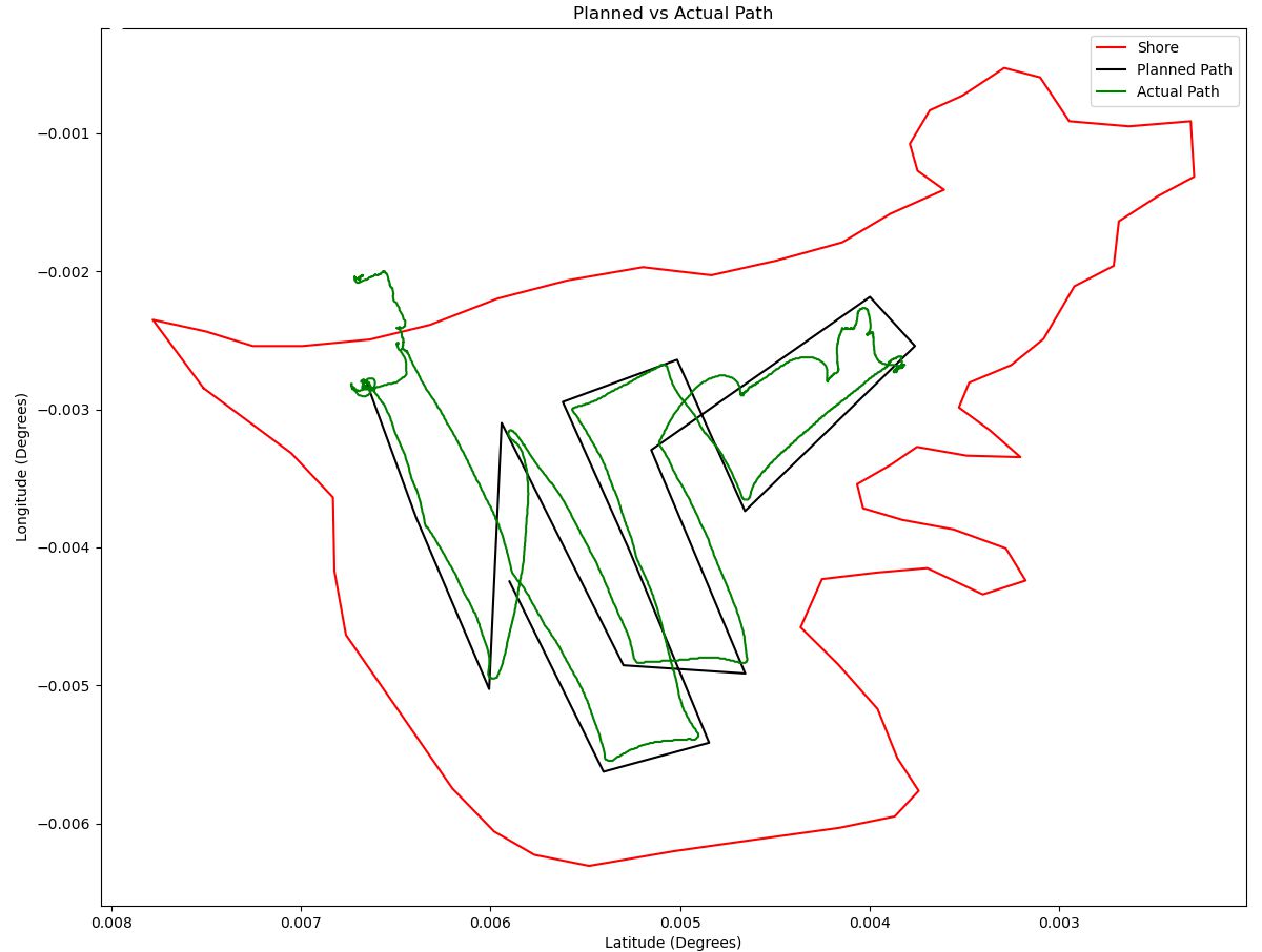
This shows the planned waypoint mission vs the actual recorded path the boat traveled via GPS. Again, GPS significant figures omitted for privacy. The red line is the shore, traced over via a satellite image. I make this waypoint mission via QGroundControl as a GUI, but the boat itself doesn't run ardupilot. It's a fully scratch written flight controller running on a Teensy 4.1 microcontroller.
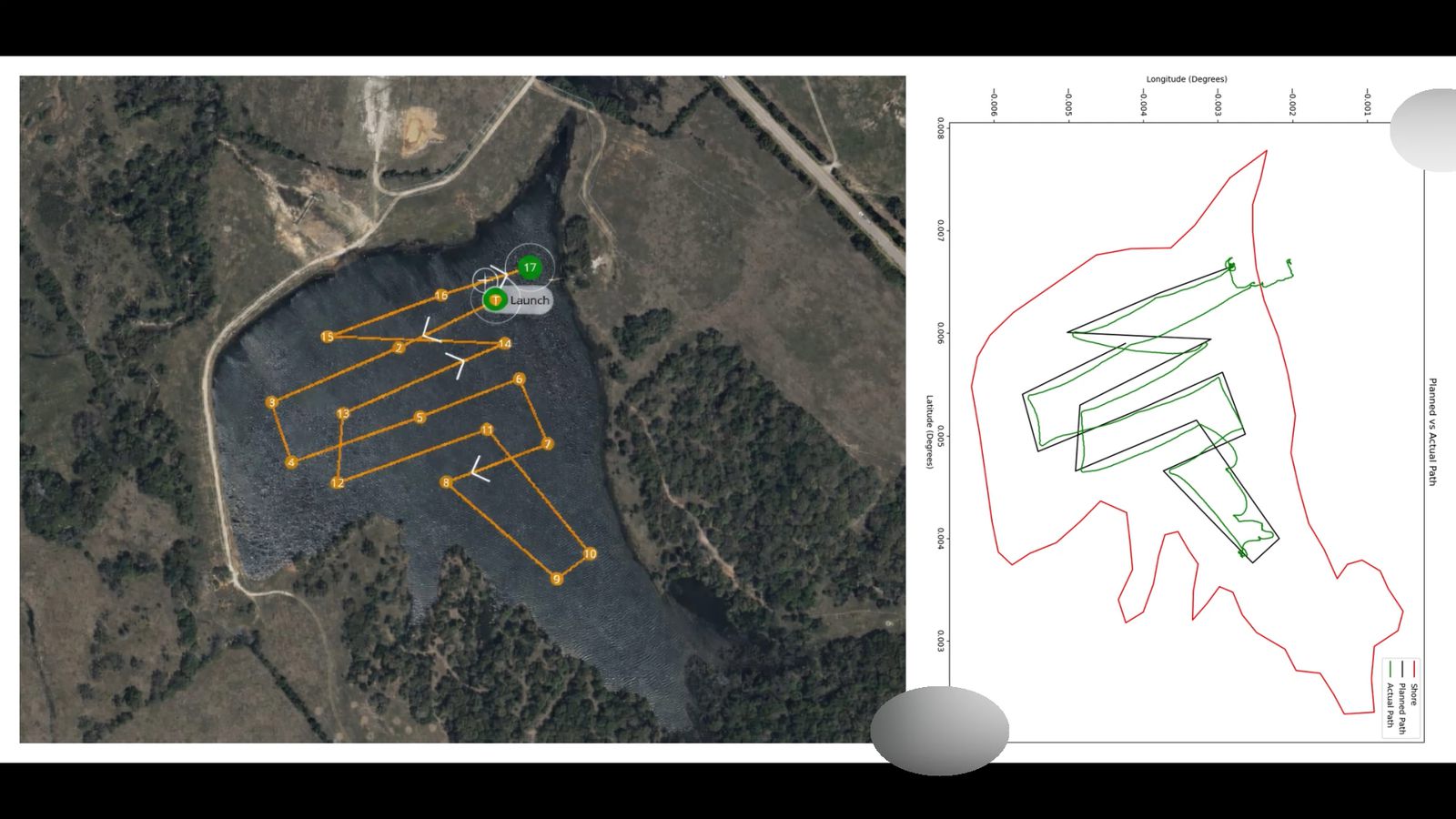
The plotted mission vs the plan on a satellite image in QGroundControl.
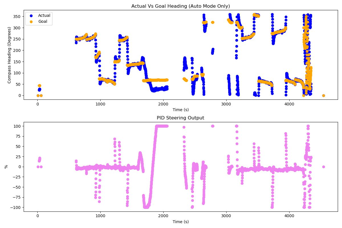
These plots show the actual compass heading, goal heading, and steering output value over time. It's running an autonomous waypoint mission with the error in compass heading feeding into a PID loop that controls the boat's steering. Actual vs goal heading track pretty well and respond to step inputs without overshooting too bad. There's a few cases where they diverge, as the boat gets stuck in weeds. Specifically at about 2000 seconds, you can see the actual heading is not getting closer to goal, even though the PID output was pegged at the maximum. Gaps in this data are when I took over manual control.
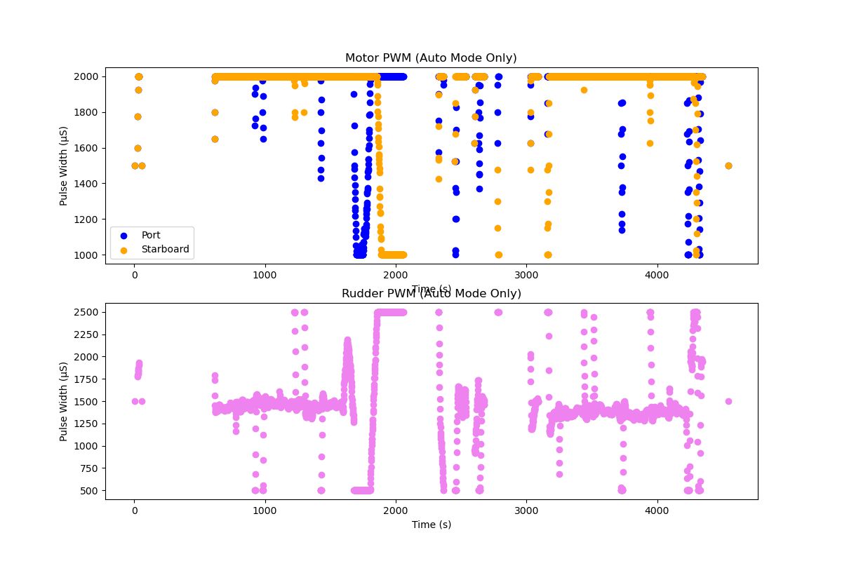
This shows the PWM signals going to the motor ESCs and the rudder servo. There's two motors that steer with differential thrust when the vehicle is way off course and needs a lot of quick turning authority. The twin rudders are driven by one servo, doing all of the work fine tuning to keep her straight during long straightaways. In these plots, you can see that both motors are pegged at full steam ahead for most of the time, except the sharp turns on waypoint changes where the inside motor slows down. In a few cases, for extreme steering commands, the inside motor goes up to full speed in reverse. The servo spent most of its time bouncing around 1500 (centered) making only minor adjustments, then steers to the extremes only on hard turns.
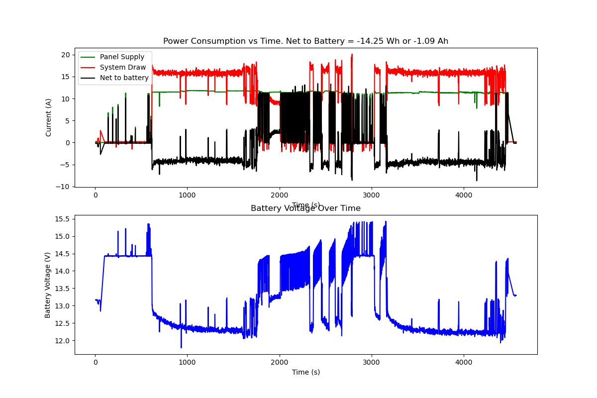
Here's the power system data. The solar panels provide power to the batteries and the load through a charge controller. I have current sensors on both the input and output of the controller, allowing me to measure the solar power in and the system draw out of the batteries. For most of this mission, there was a slight net discharge on the battery at about 5 Amps out. The two 10Ah batteries in parallel have enough capacity to run for 4 hours at that rate. During some of the stops while stuck in weeds, there's a significant net charge into the battery, and the final voltage at the end of the mission was only a little under where it started.
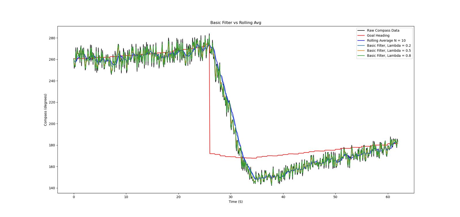
I zoomed in on some data from a step input where the goal heading changed as a waypoint was reached, then I retroactively applied a few different algorithms to the boat's measured compass heading to see which might be better to feed into my steering PID loop. I currently use a rolling average of N = 10 measurements to smooth out the data so the rudders aren't constantly jerking around due to compass noise. The downside of this rolling average is that it's slower to respond to real sudden heading changes that aren't due to noise. I tried out this exponentially weighted moving average algorithm to see if it would improve the response:
𝑥(𝑘) = (1 - 𝜆)*𝑥(𝑘 - 1) + 𝜆𝑢(𝑘)
Looking at the chart, High values of lambda don't do much to filter out the noise. But the Lambda = 0.2 line is about as smooth as the rolling average while responding a little bit faster. This is because it weights more recent measurements higher than a simple rolling average, while maintaining most of the smoothing effect. I'll look into exploring this more in the future, or ideally implementing a kalman filter including gyro data and gps heading as well. But the current compass only, rolling average PID loop works well enough for now.
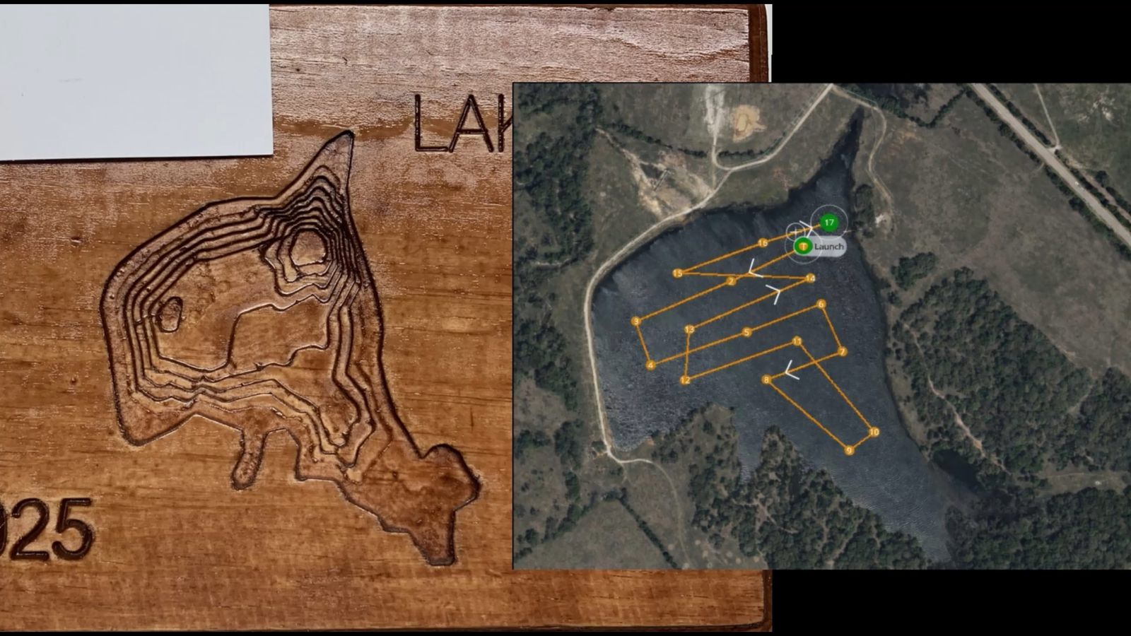
The wood carving vs the mission plan.
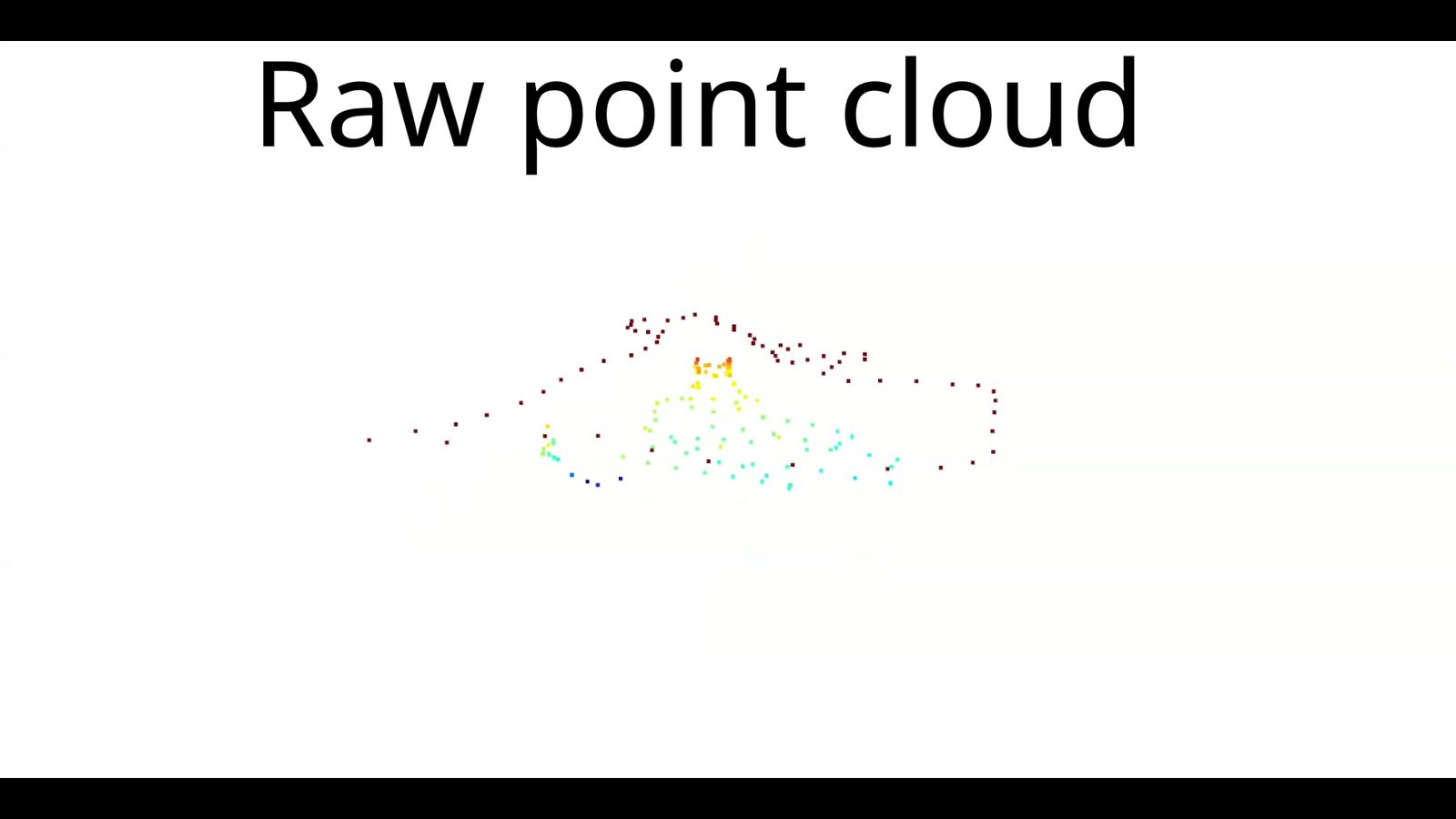
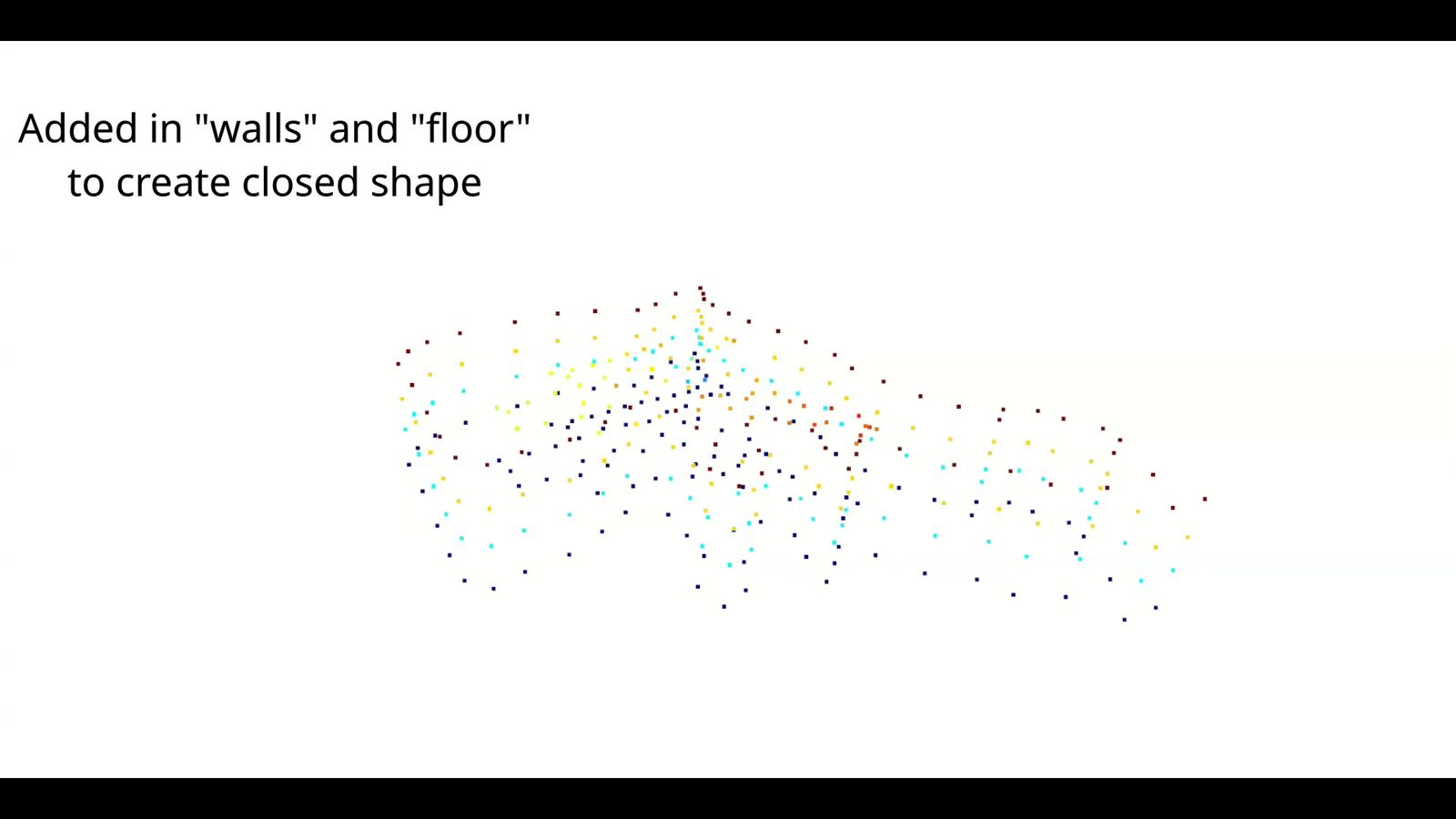
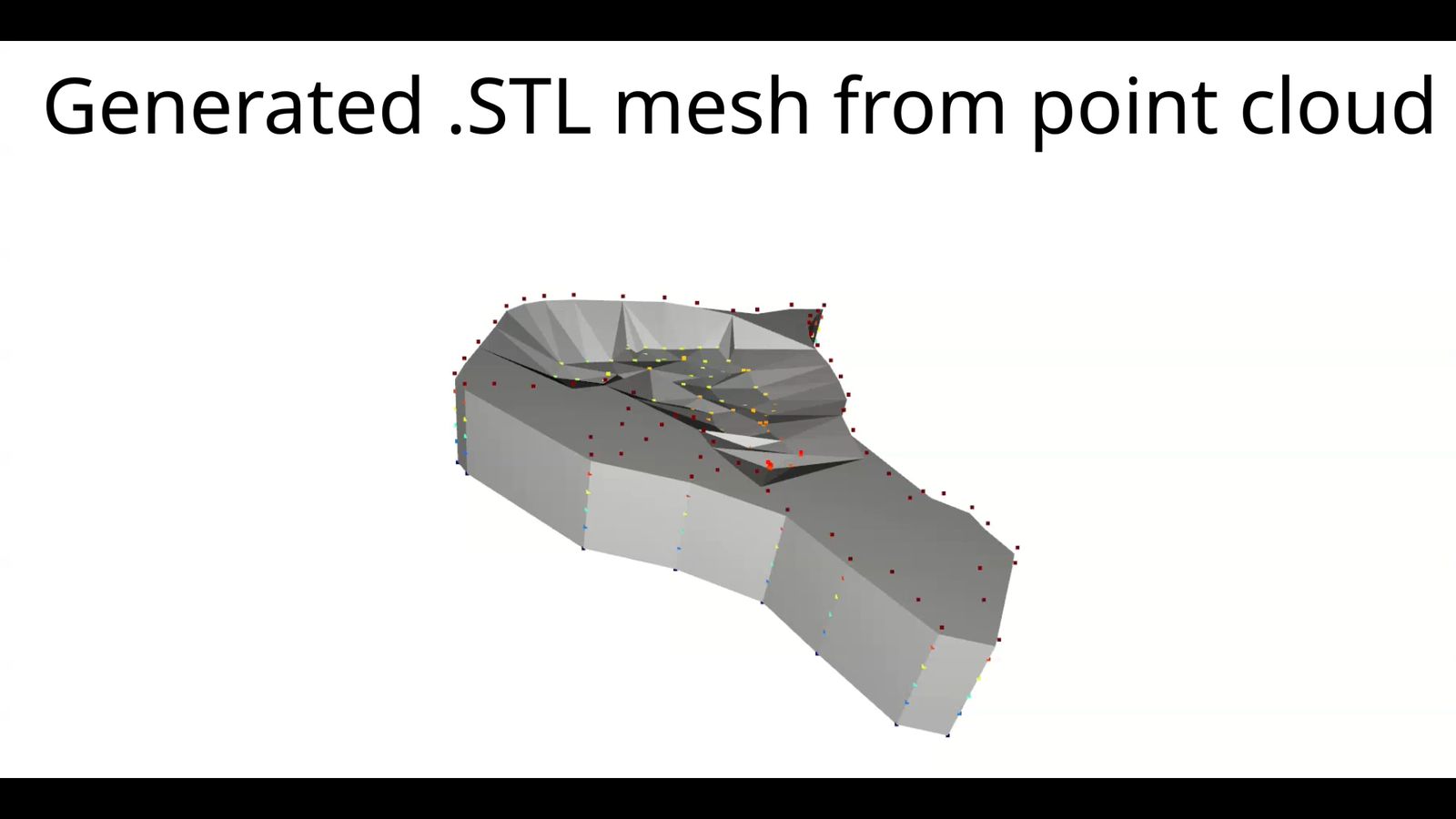
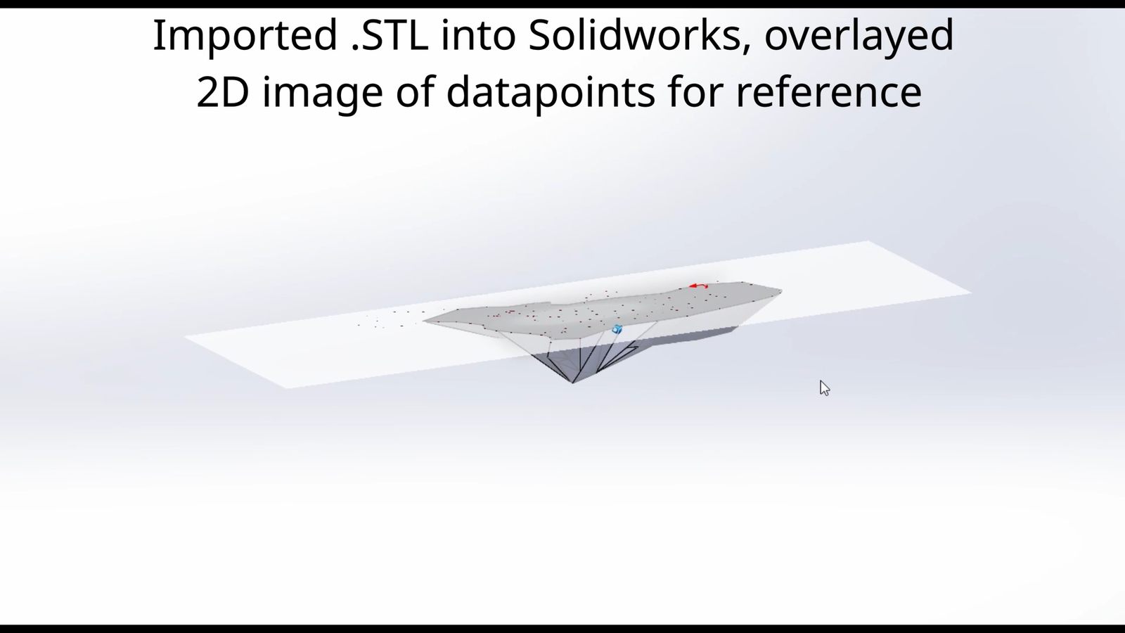
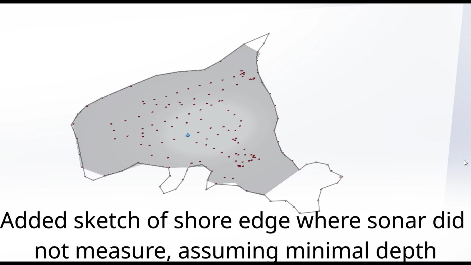
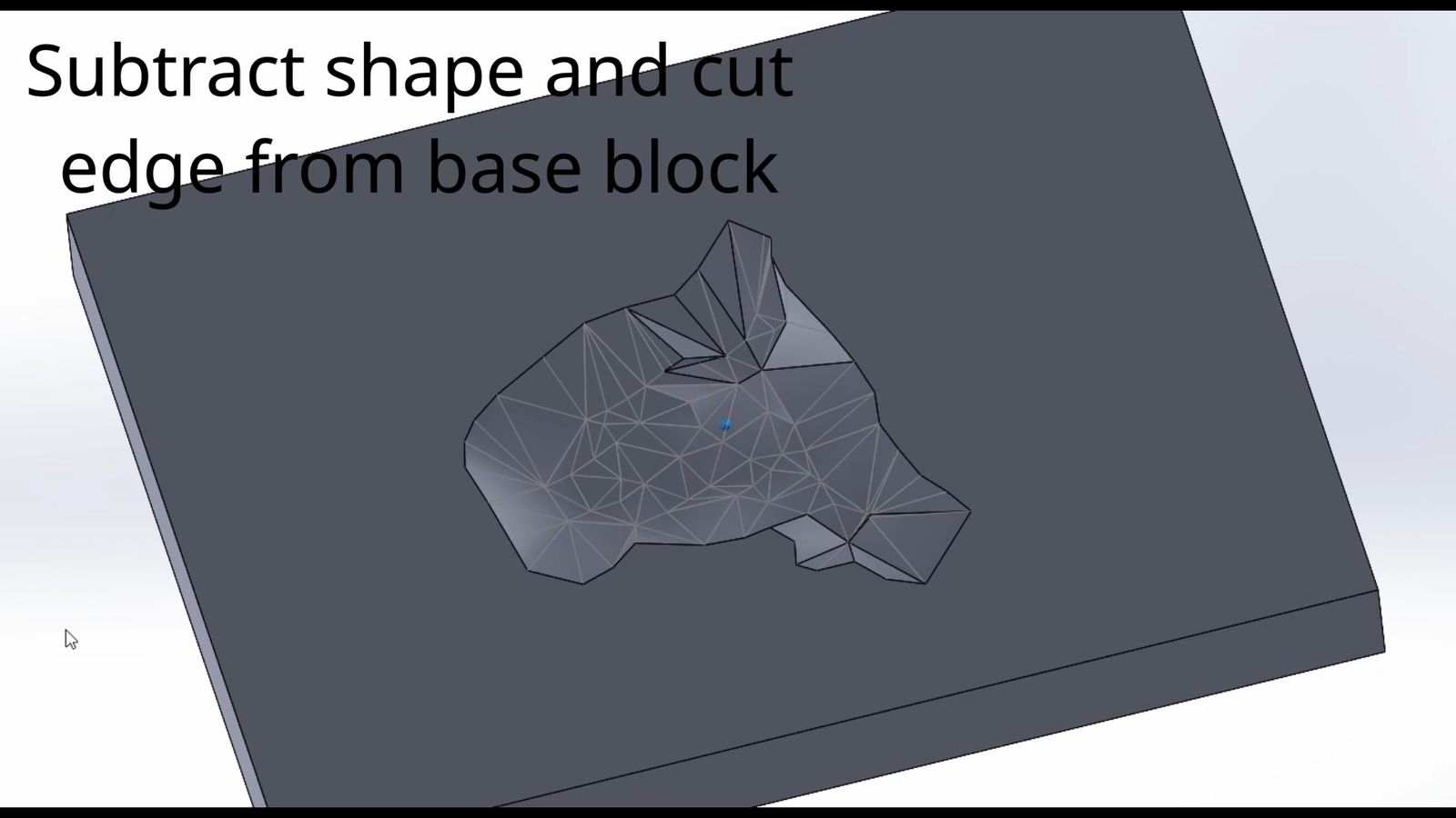
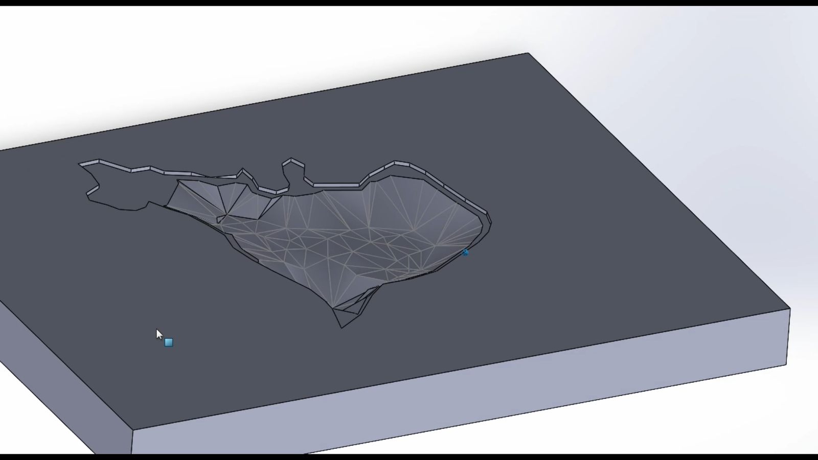
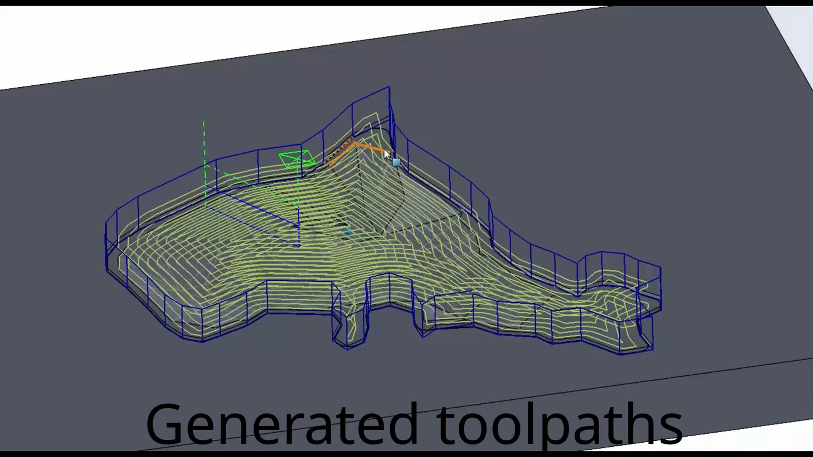
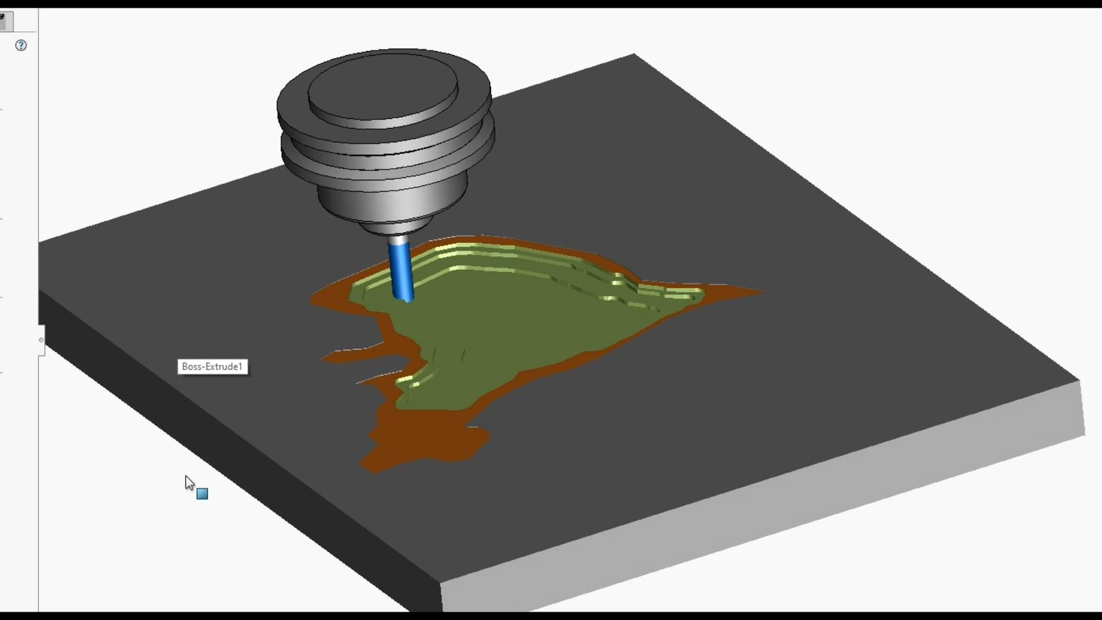
The process of going from a pointcloud of depth measurements to gcode for running the CNC router. Code used for this is on the github page.
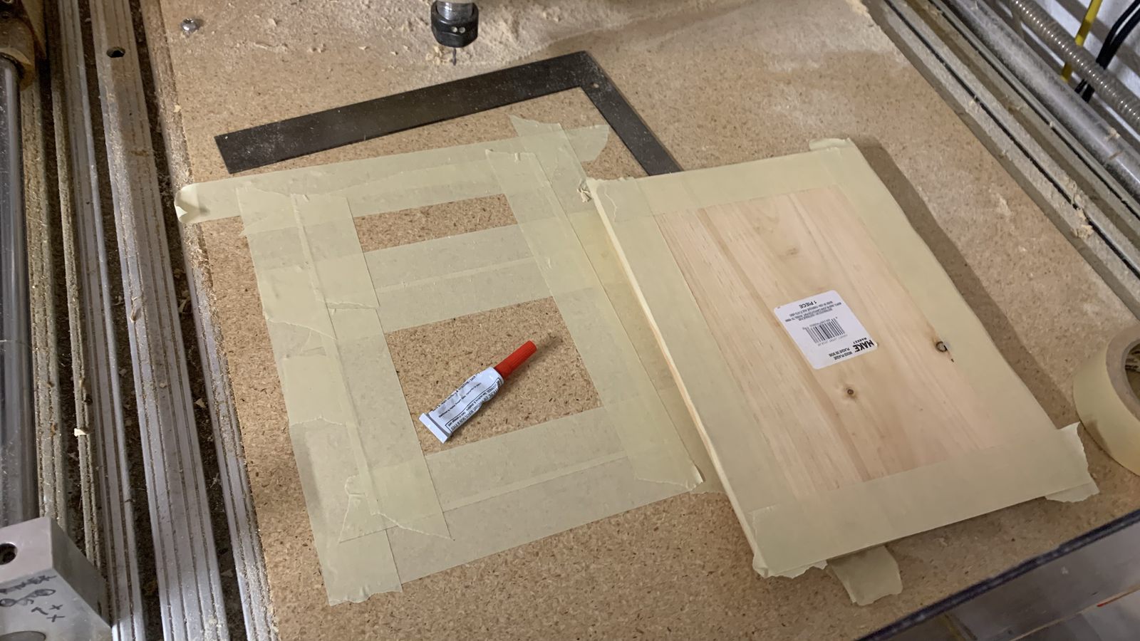
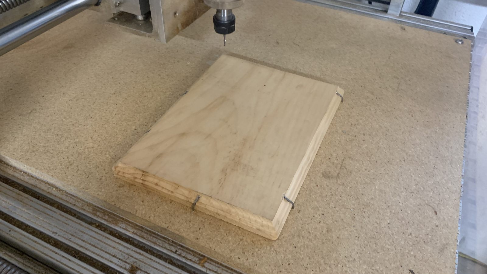
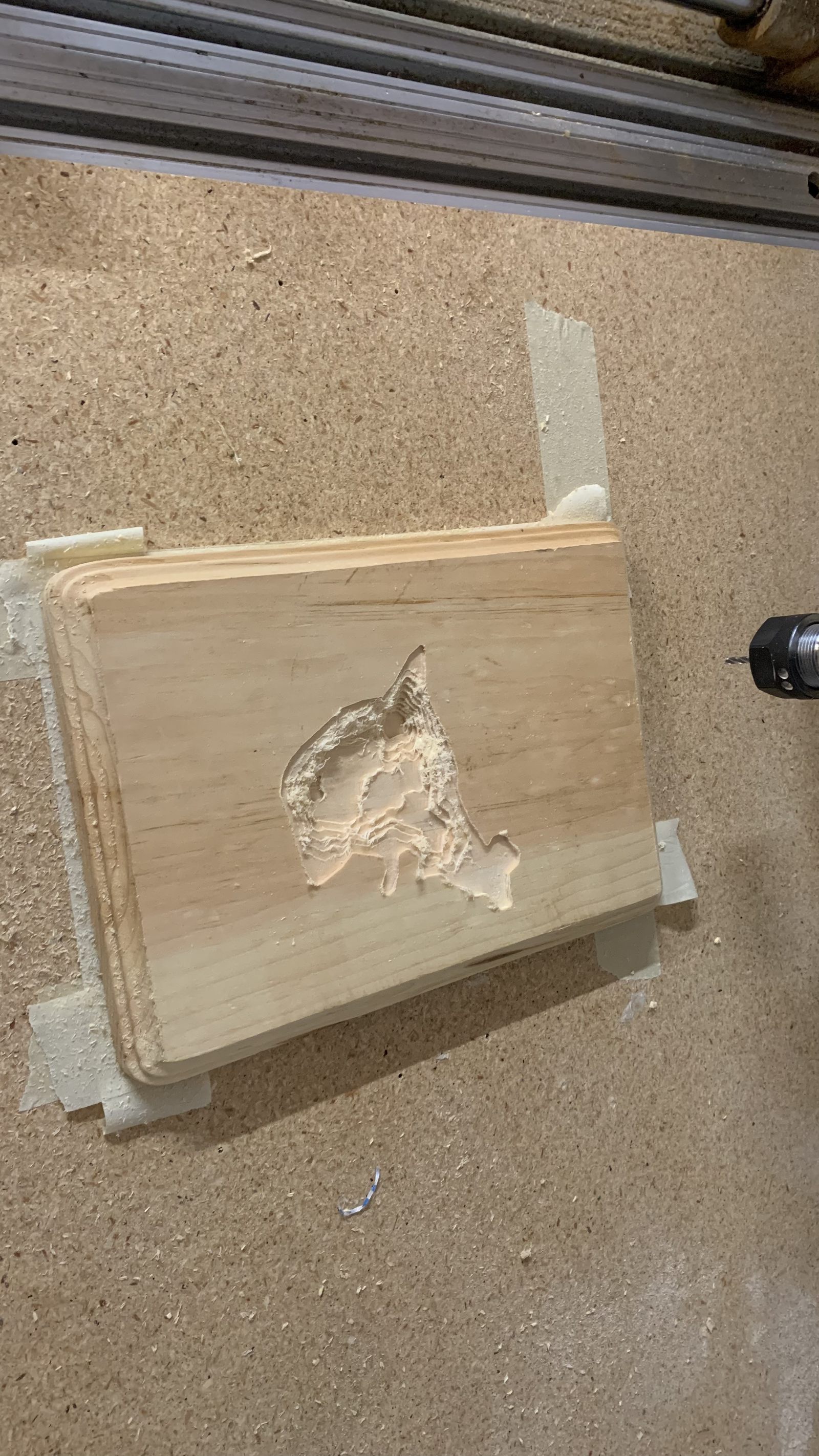
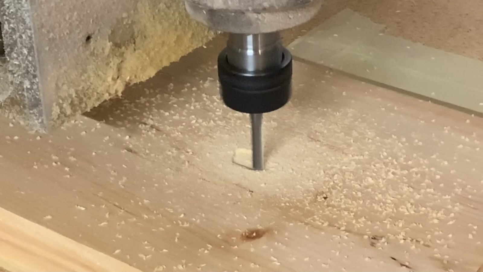
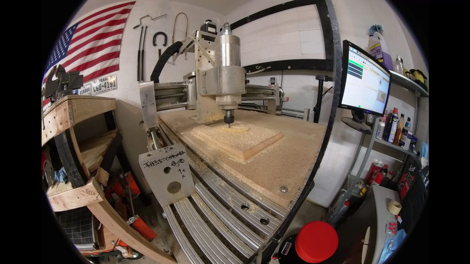
Running the router.
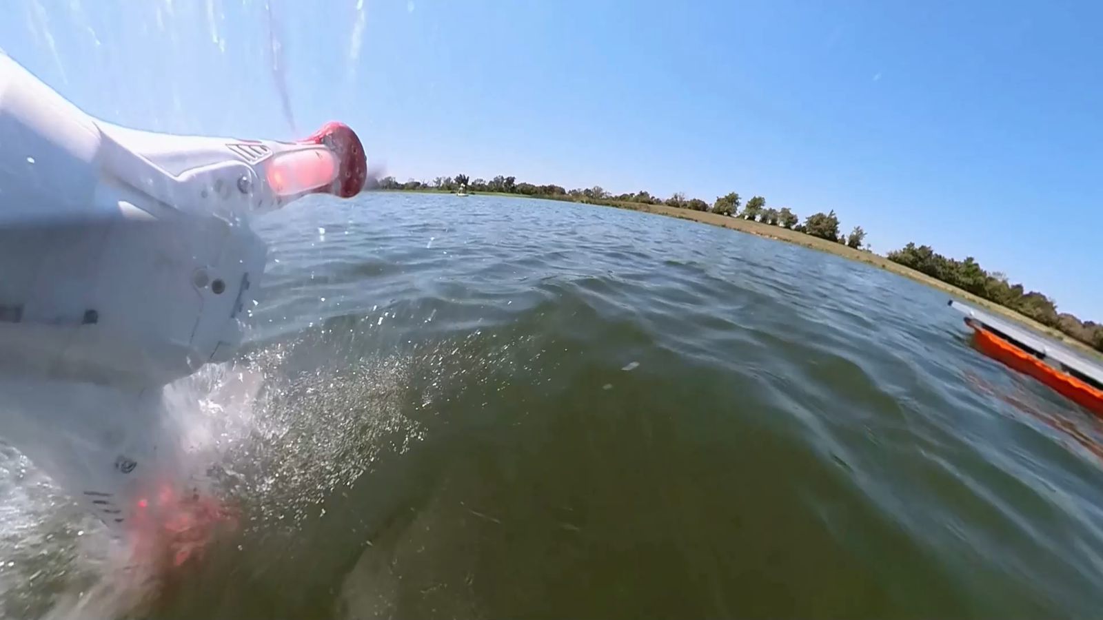
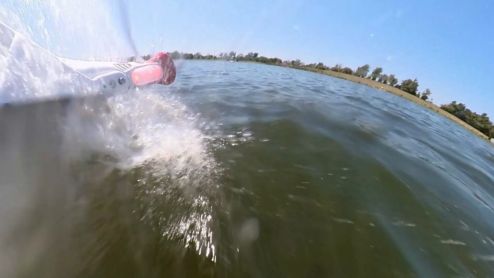

Oops