Autonomous 6x6 Rover Build
Penny Rover Build
I called this project Penny because it was inspired by NASA's "Percy" (Perseverance) rover, but it's way cheaper. The motors are automotive 12v windshield wiper motors, all used and from different manufacturers. They're brushed, geared down with a worm drive, and have an internal mechanical switch that closes once per revolution. The worm drive means I don't need brakes, and I was able to use the switch to measure RPM for low speed traction control. It's powered by an ebike battery (sketchy) and navigates with a gps and compass. It has a rocker bogie style suspension for some pretty extreme articulation ideal for low speed crawling over rocks. For now, no obstacle avoidance or other sensors. Its top speed is around 1mph and it can run for around 45 minutes.
Build and Test Video
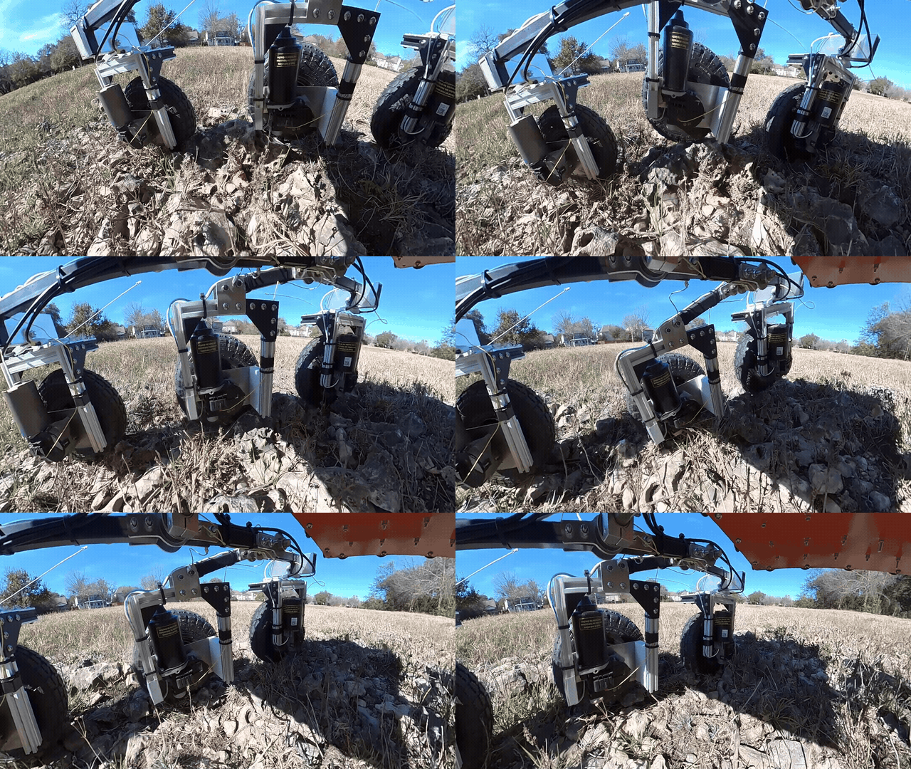
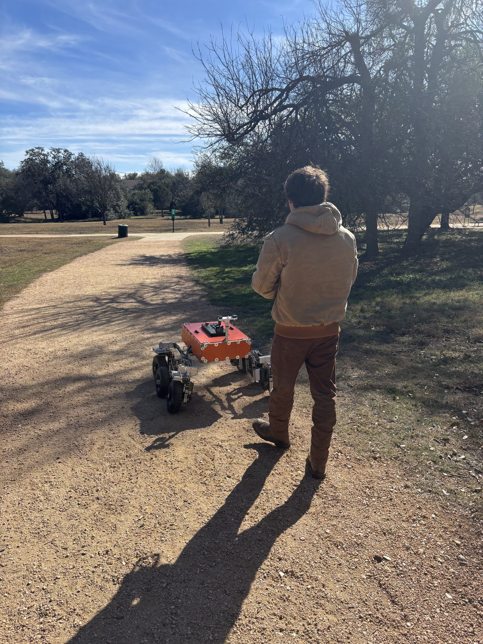
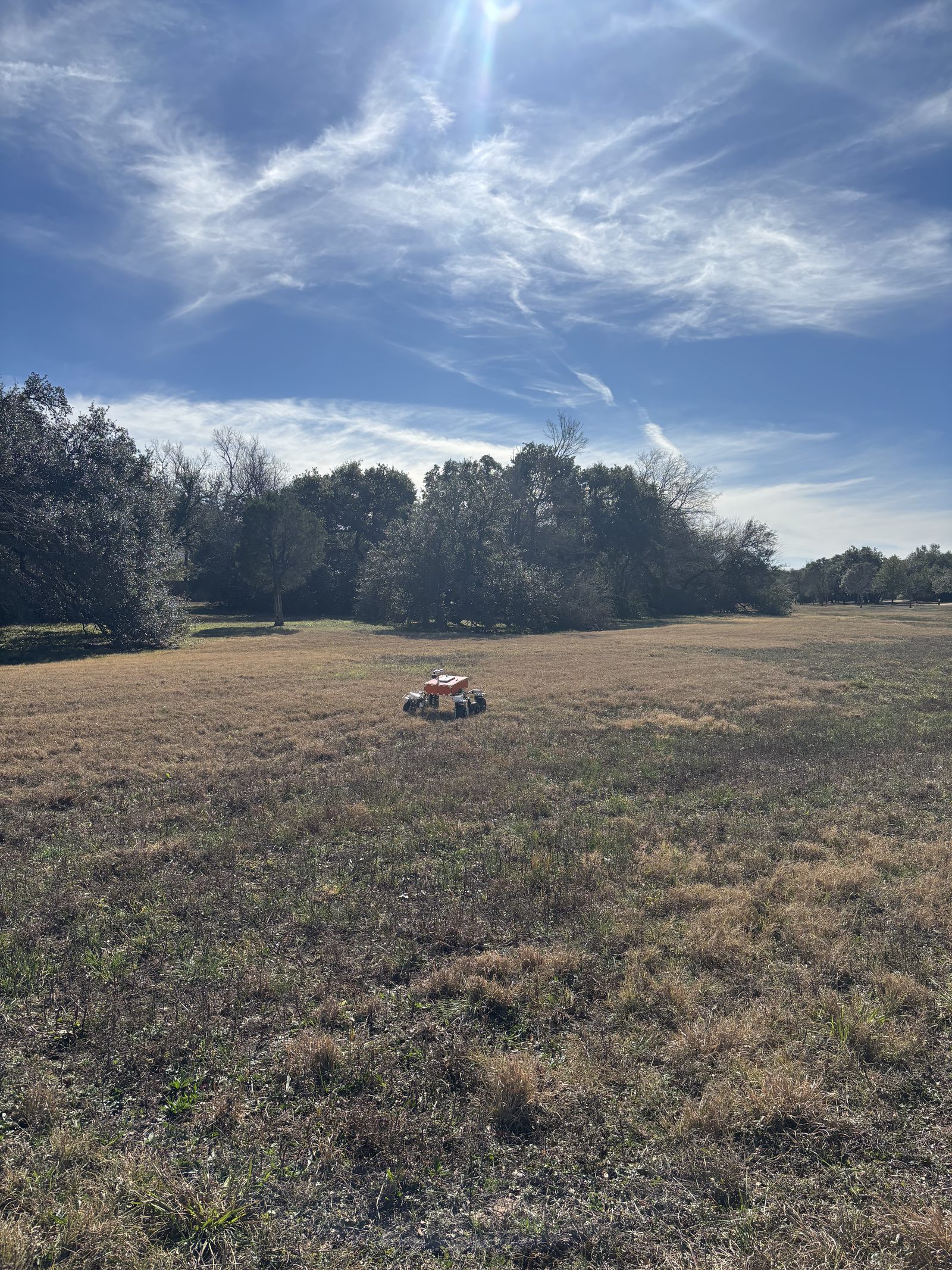
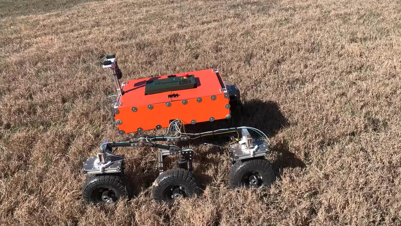
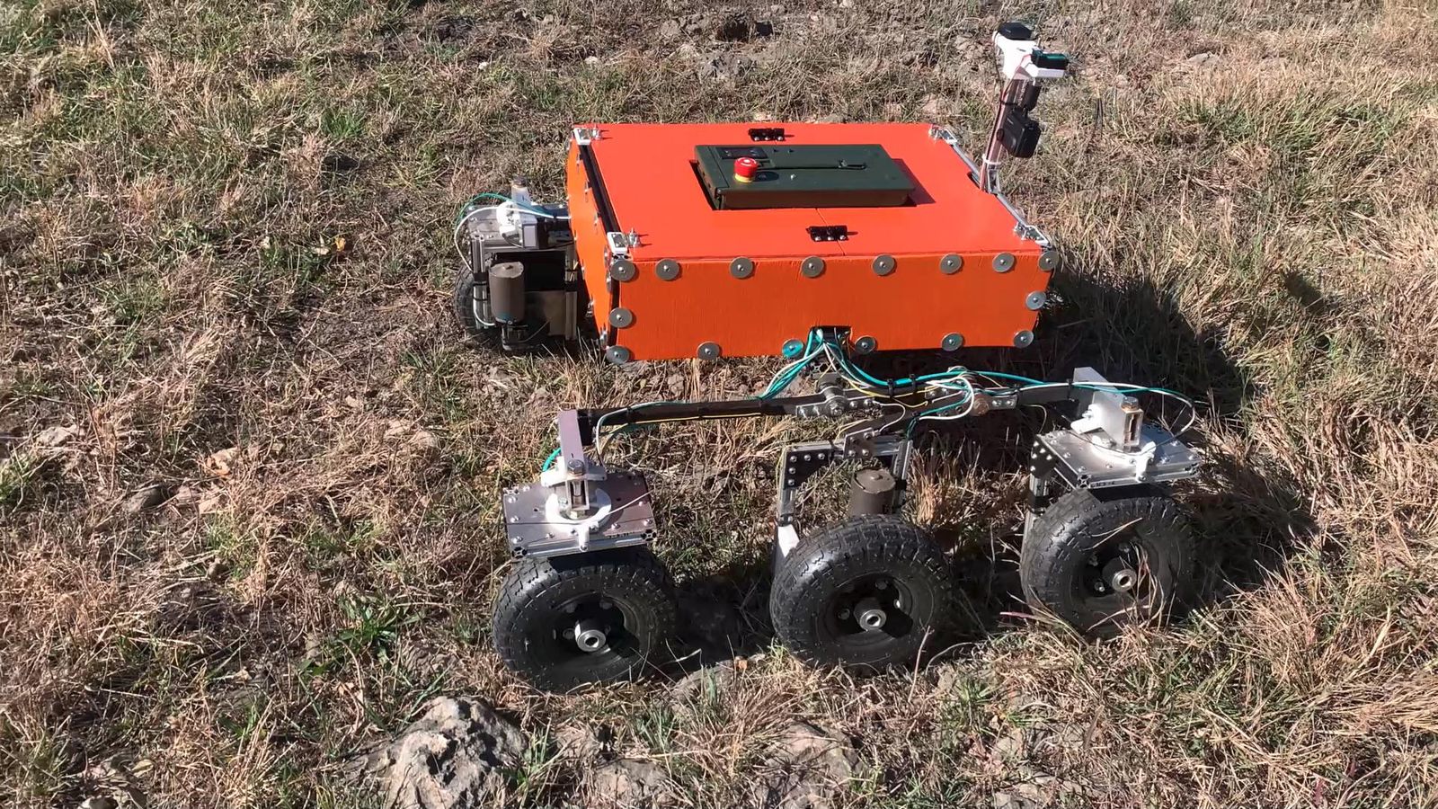
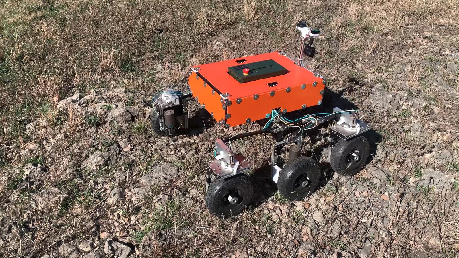
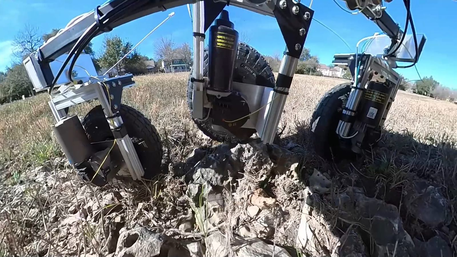
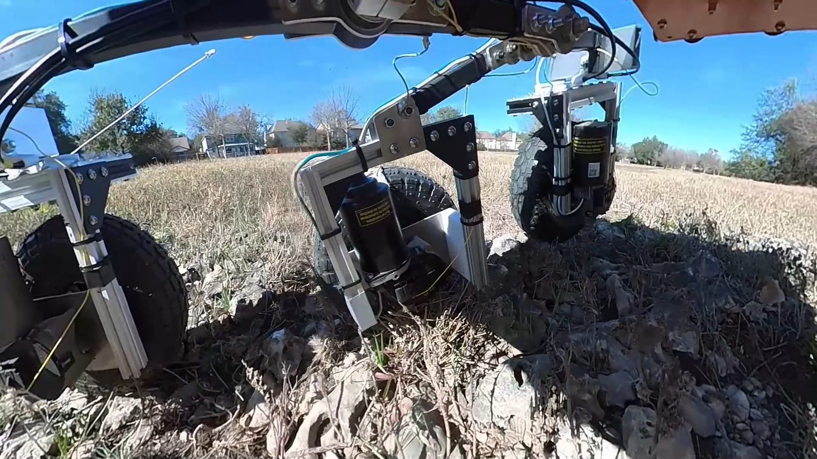
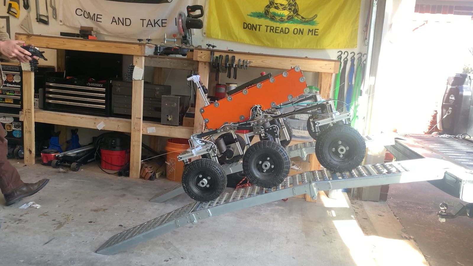
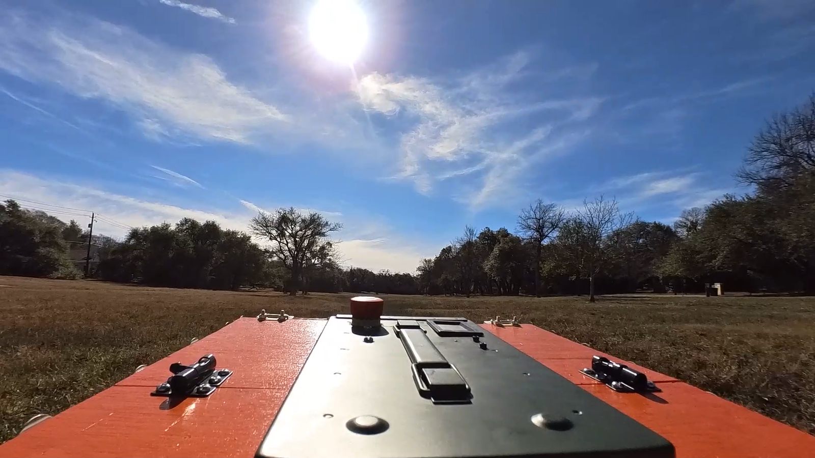
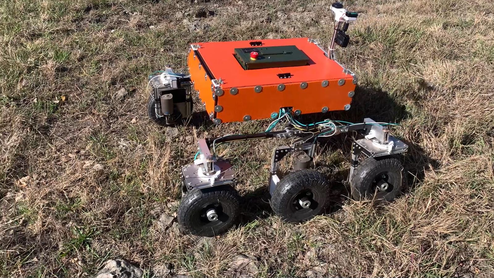
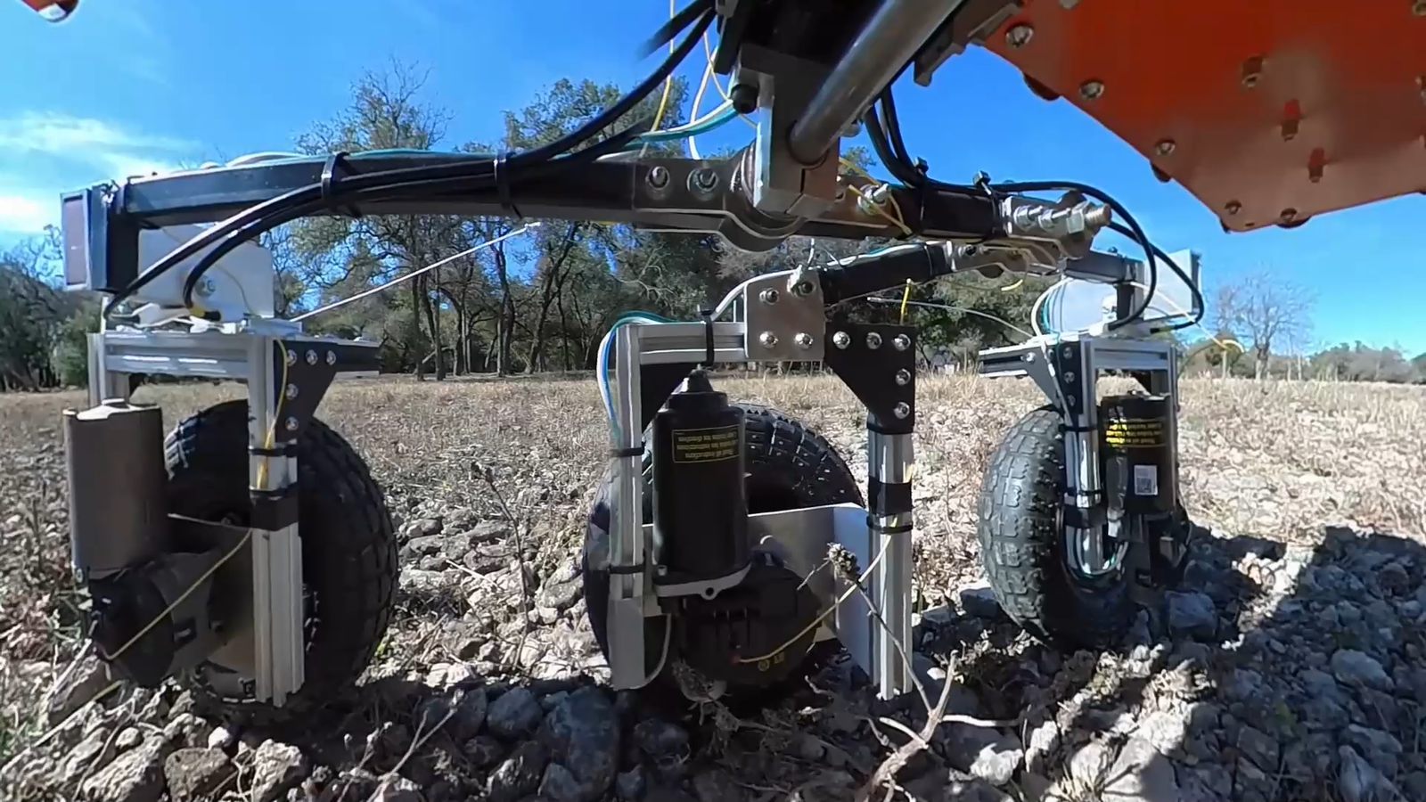
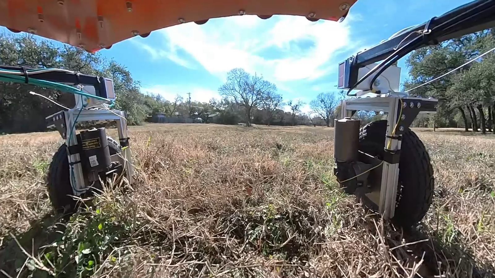
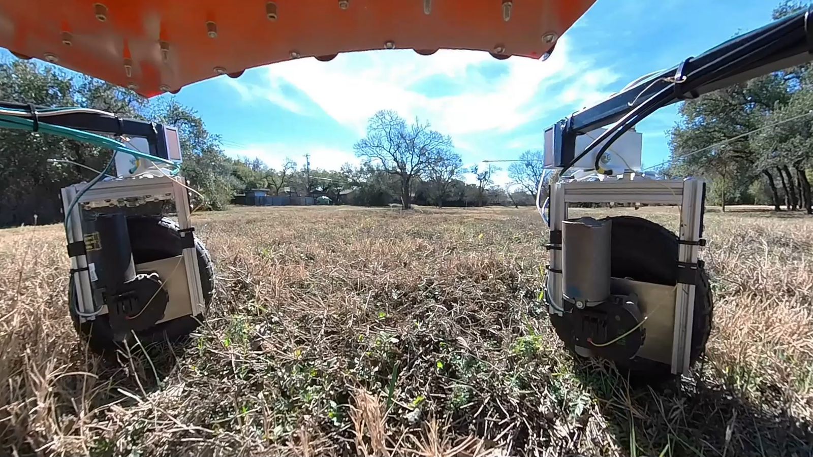
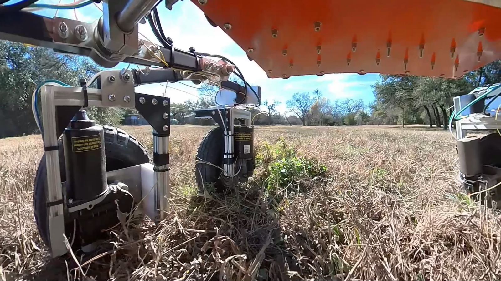
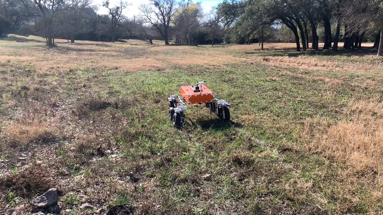
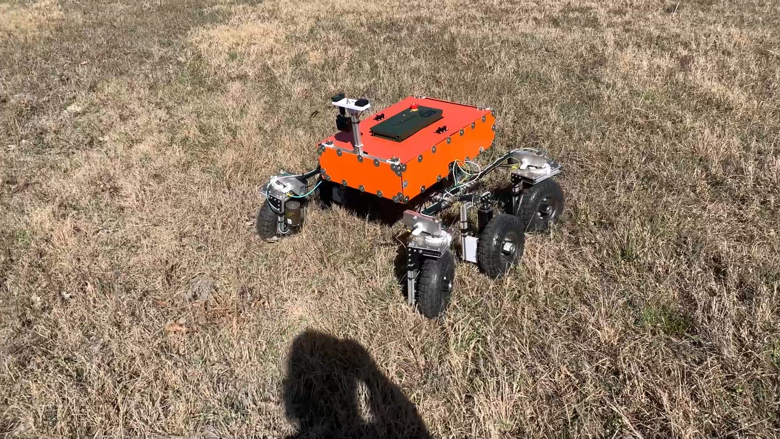
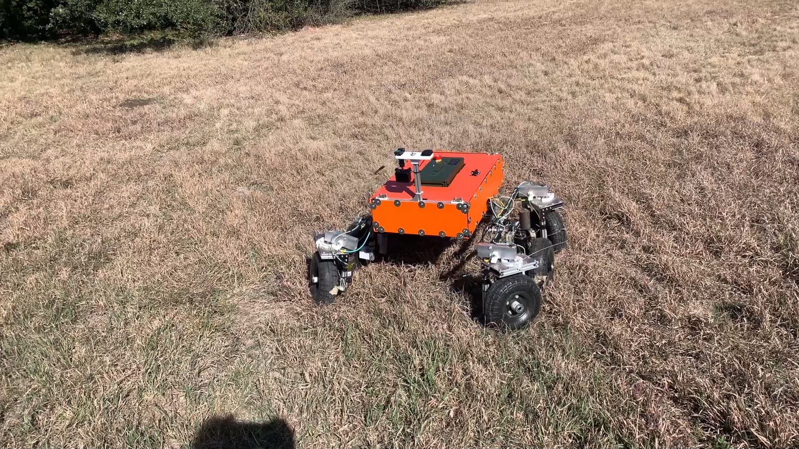
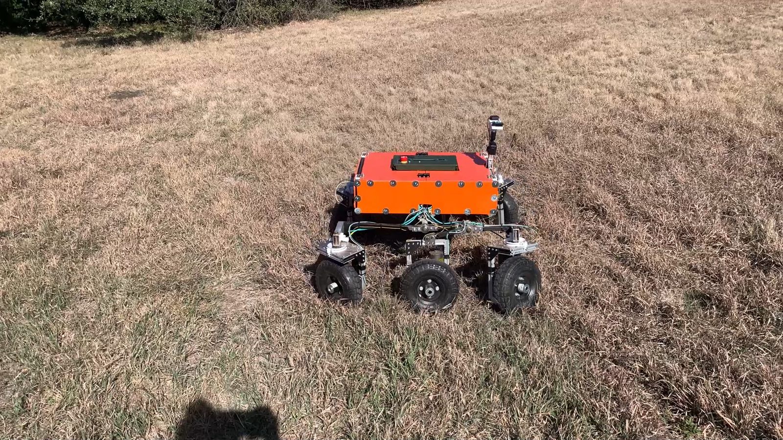
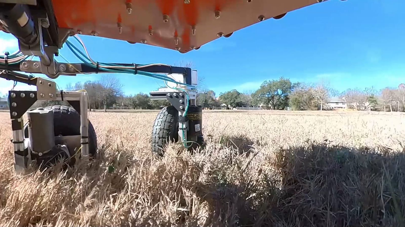
Some action shots of the vehicle on her first outdoor test run.
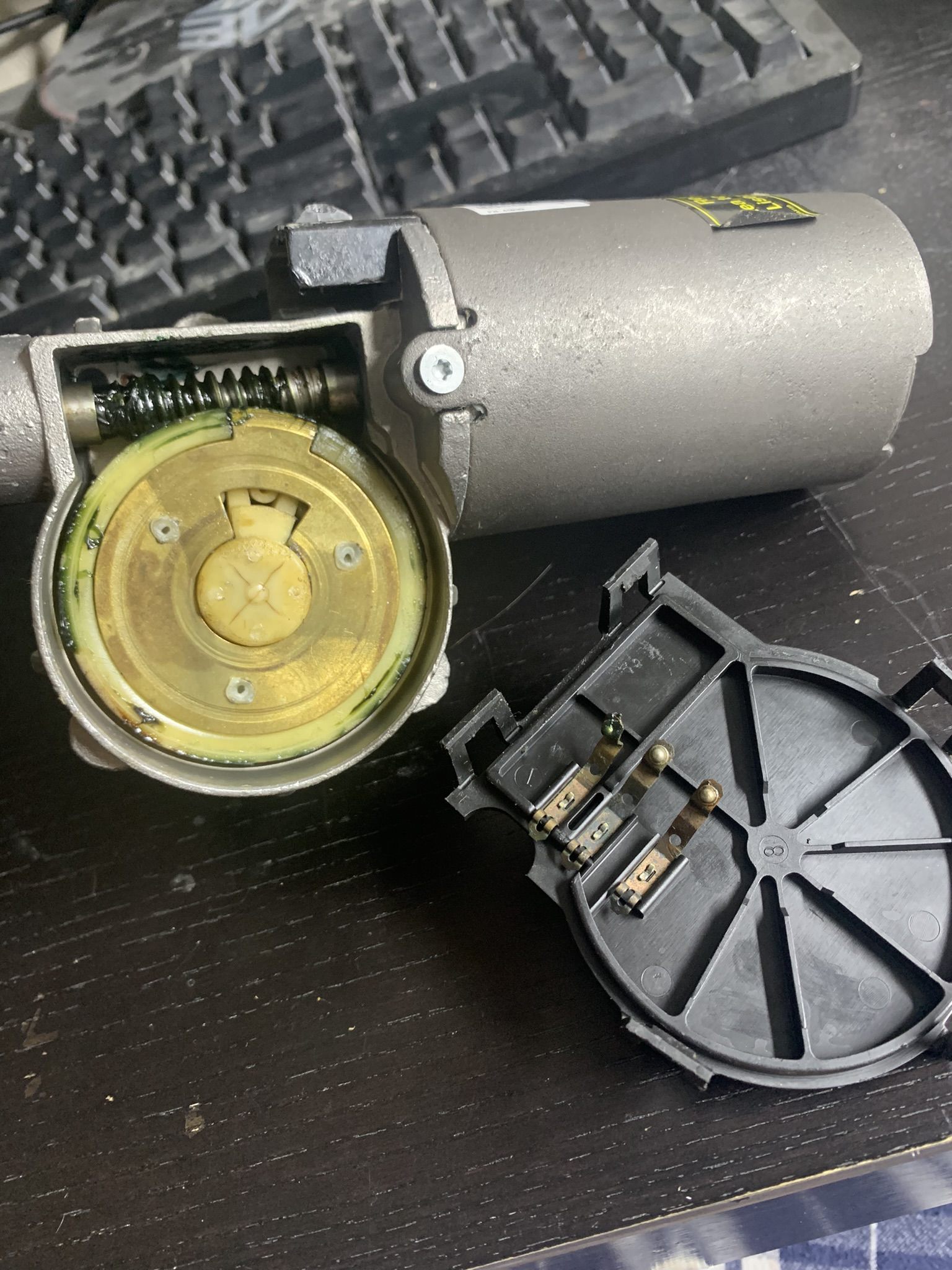
I used 6 of these automotive windshield wiper motors. Visible worm gears and position detection switches which made my traction control work.
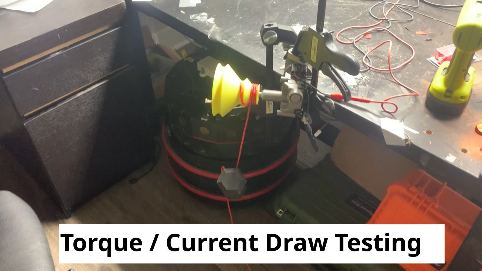
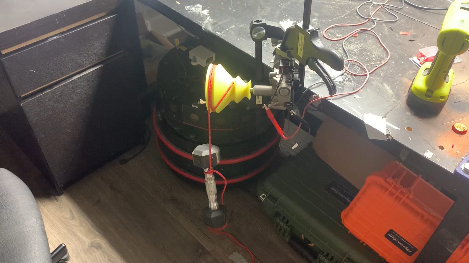
I measured the motor stall torque by hanging a known weight of a known radius pulley and trying a few different weight/radius combos while measuring the motor torque. This allowed me to put together a torque/current curve assuming a linear relationship. This let me evaluate the performance quantitatively and predict the max weight they could push up a known slope, for example.
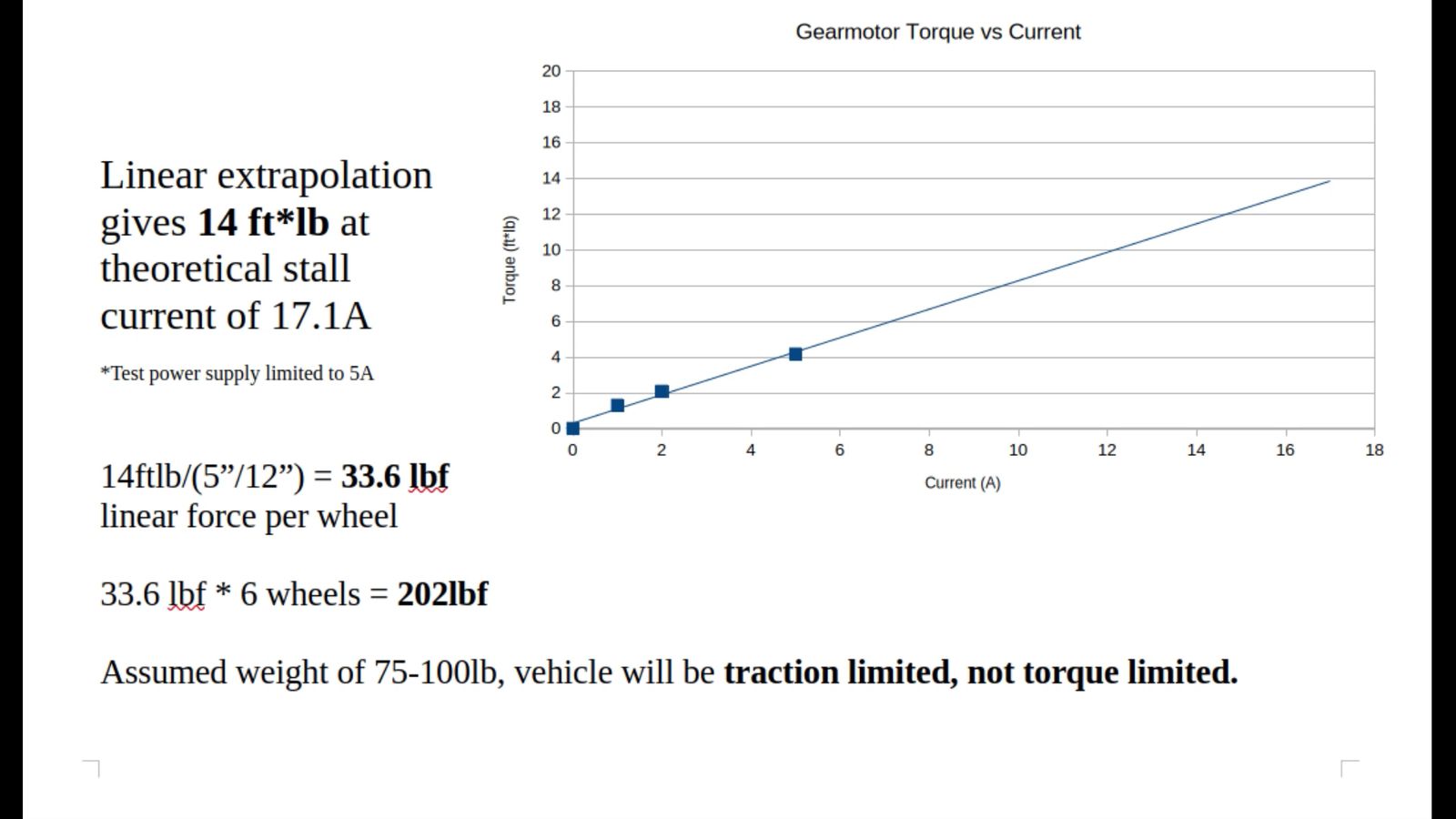
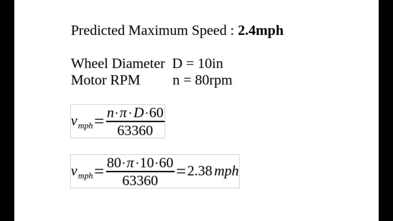
It went a little slower in real life, this calculation assumes no load RPM. Never had torque problems.
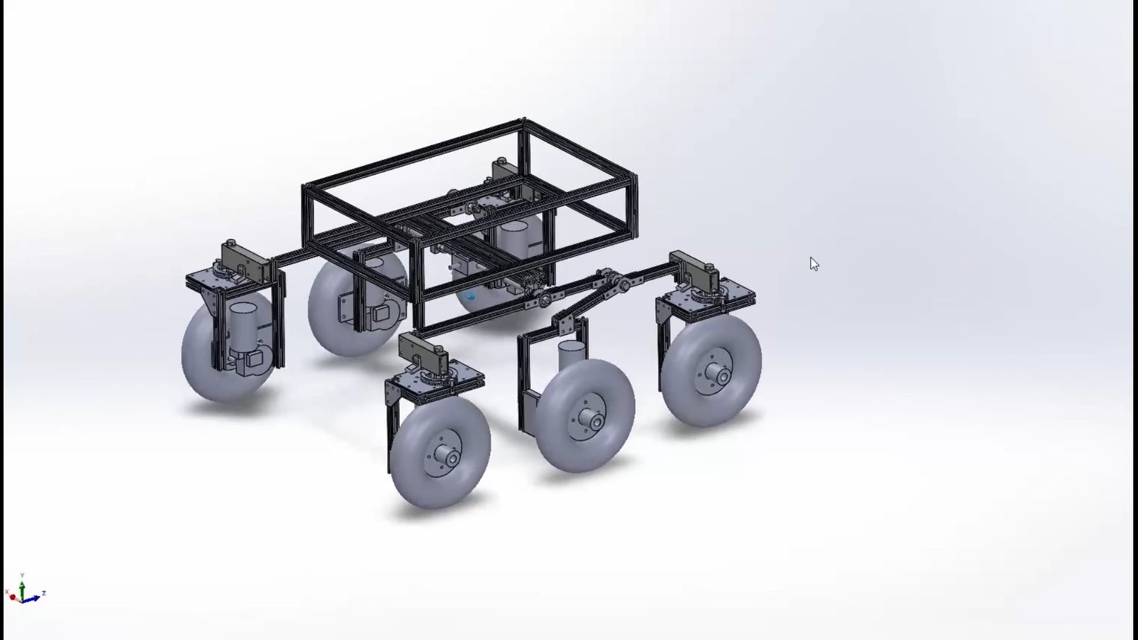
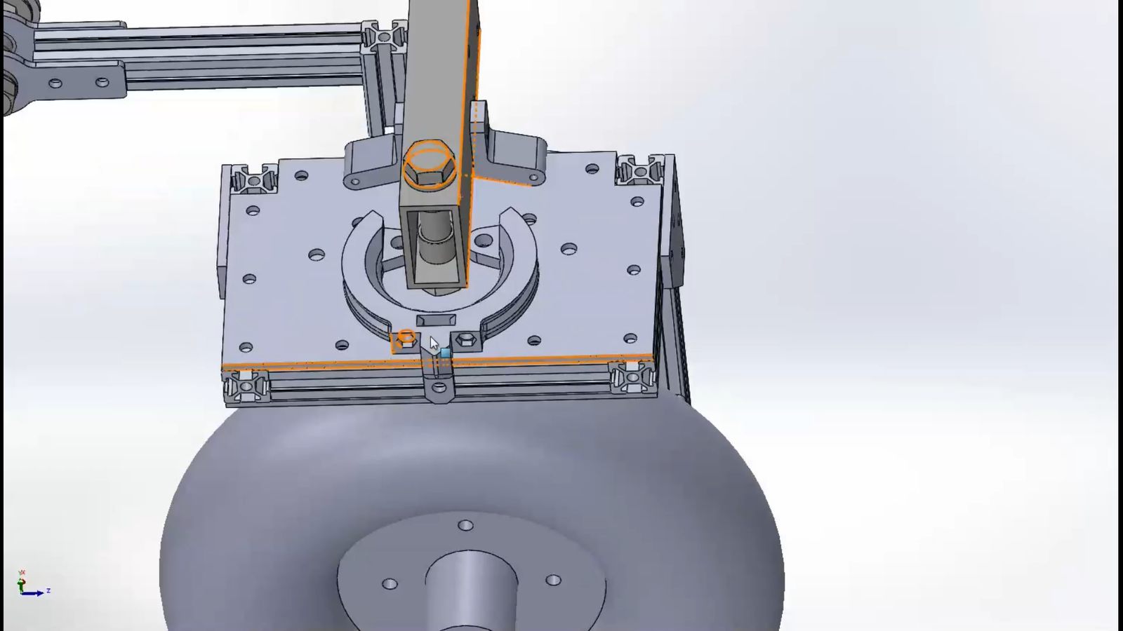
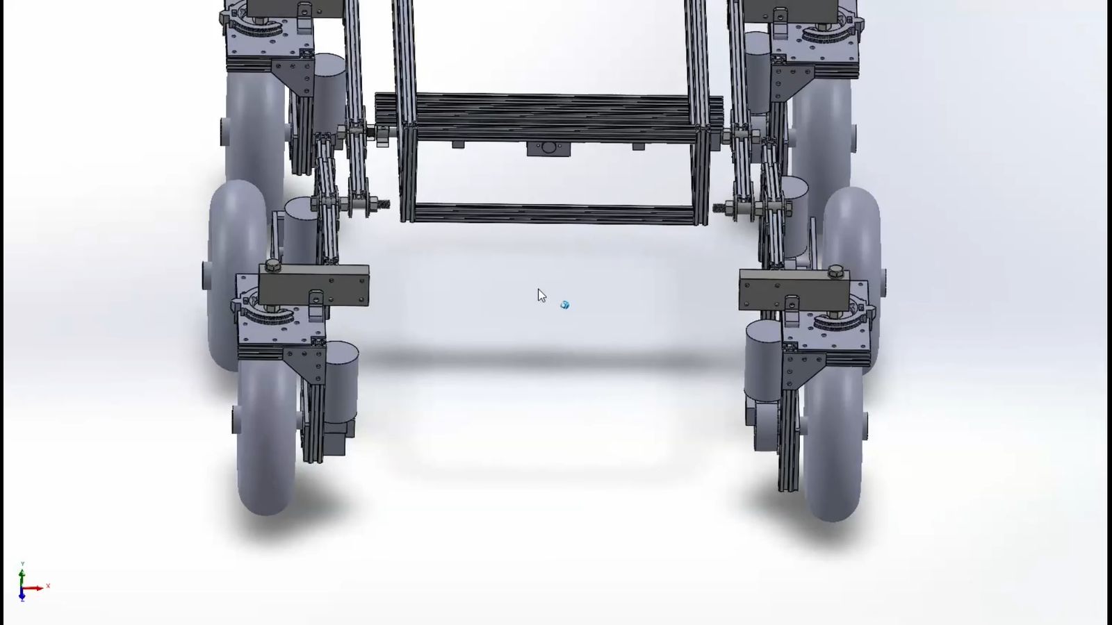
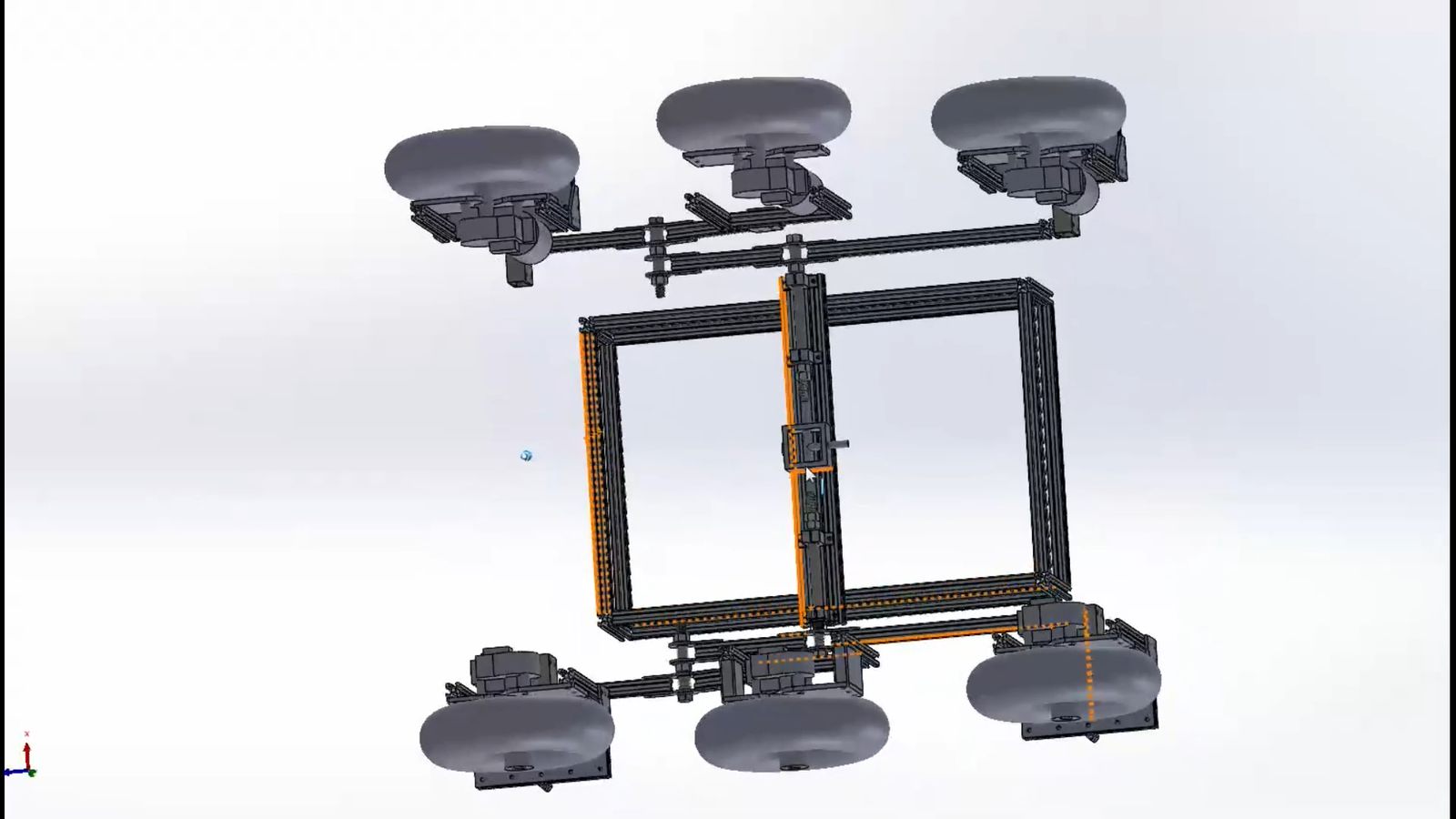
I designed the suspension and frame after predicting that this motor/wheel combo would have enough torque to drive the robot at a low speed over obstacles. All the legs were designed to be made out of 2020 aluminum extrusions and bolt on sheet metal brackets. I laid the suspension out this way so all the sheet metal brackets would be flat and require no bends. This dramatically reduced the cost, but I think the legs could've been designed to a more optimal geometry for rigidity if they weren't constrained to be parallel and flat. All the CAD is available for download in the github link along with a complete BOM.
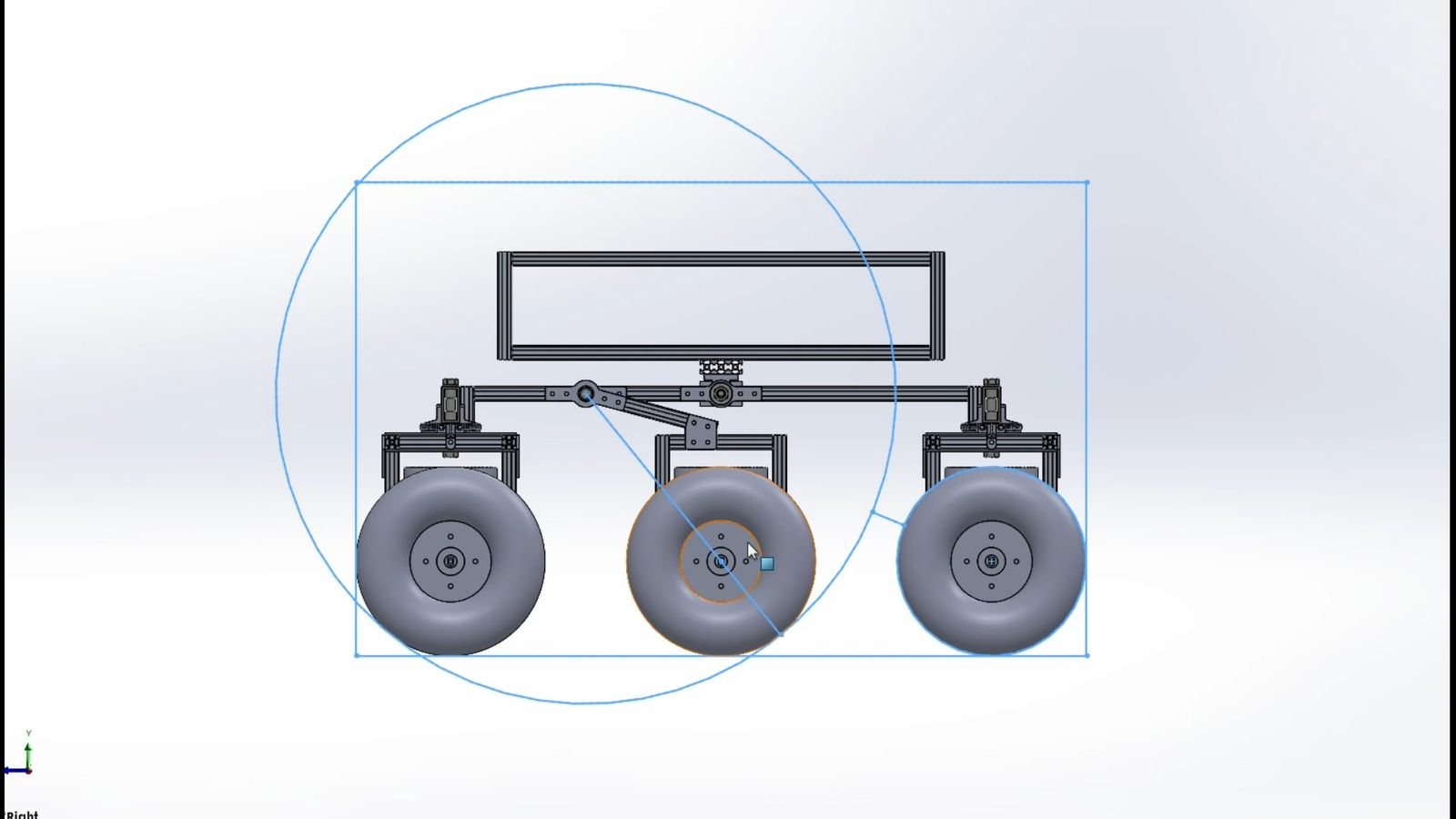
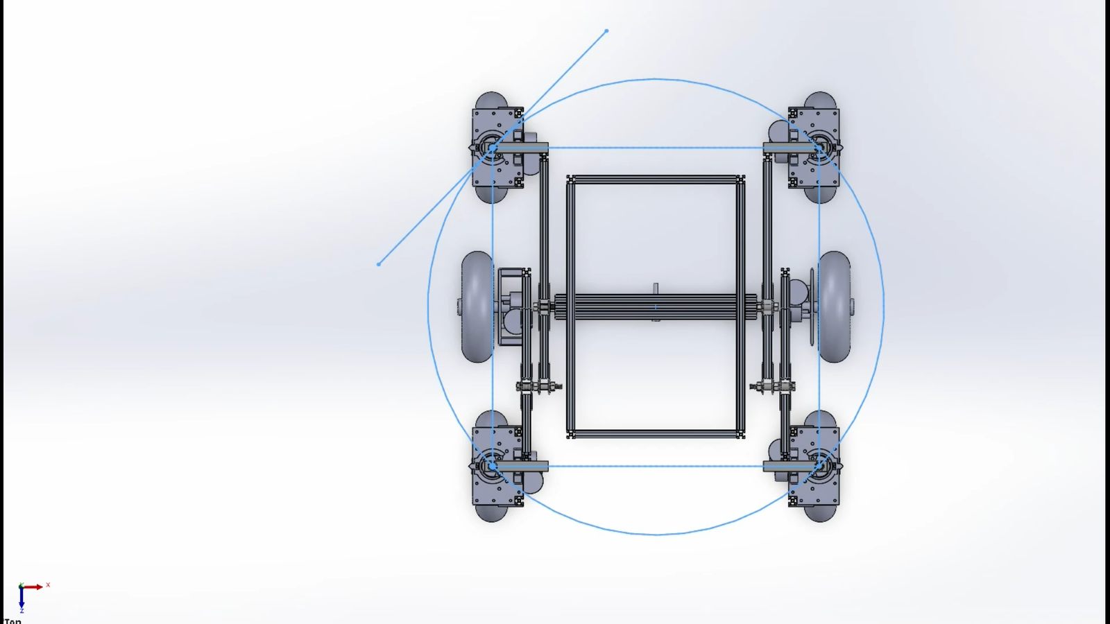
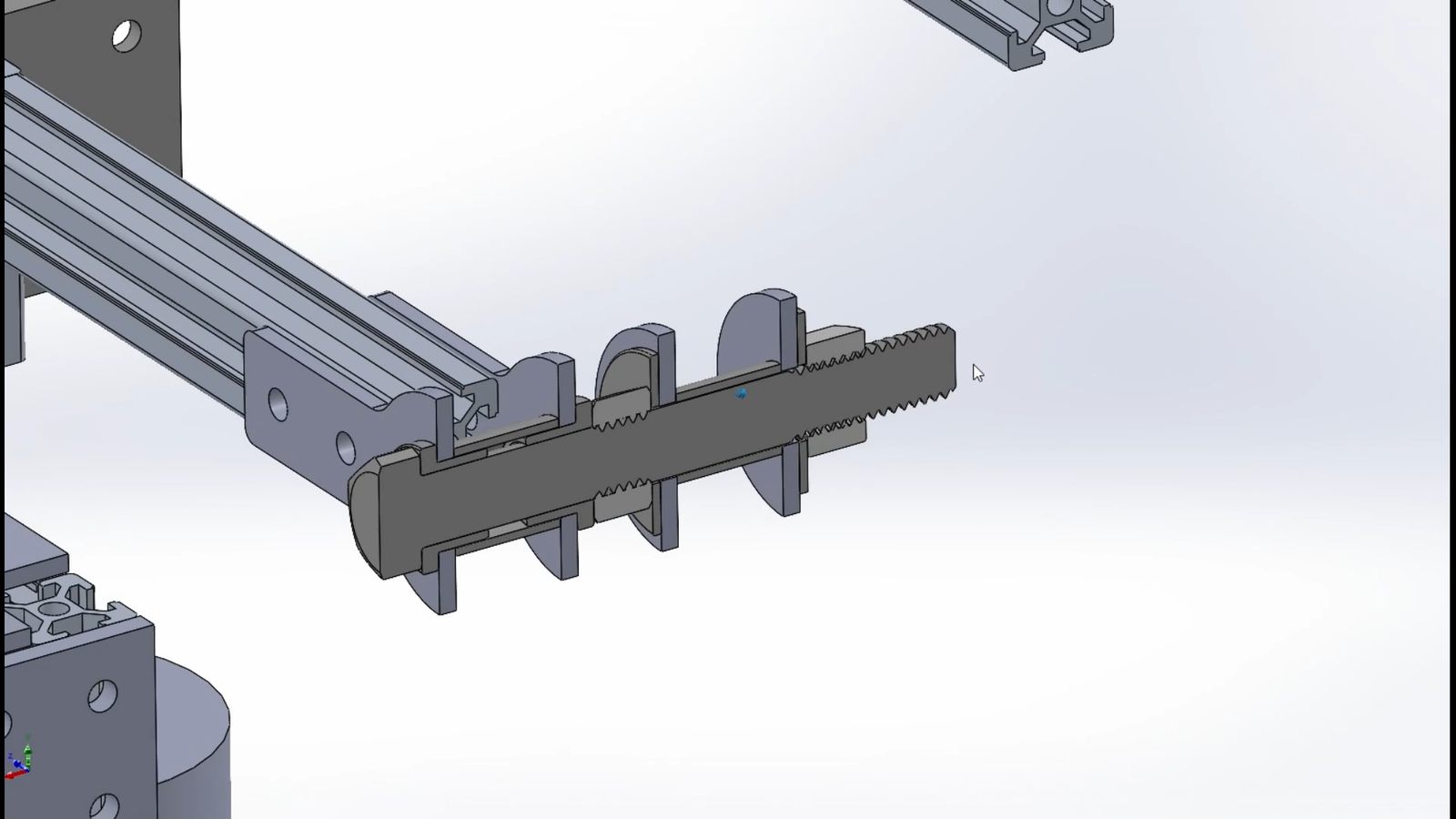
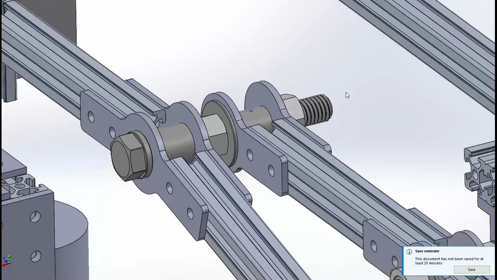
The turning wheels were all designed to be tangent to the same circle at their max turn of 45 degrees to prevent horizontal slipping during a turn in place maneuver. The suspension joints were bolts riding in bushings, with spacers and jam nuts axially constraining each joint such that the nut clamping force was not squeezing the legs together to introduce friction beyond a minimal preload to eliminate play. The joints all spin totally freely when off the ground.
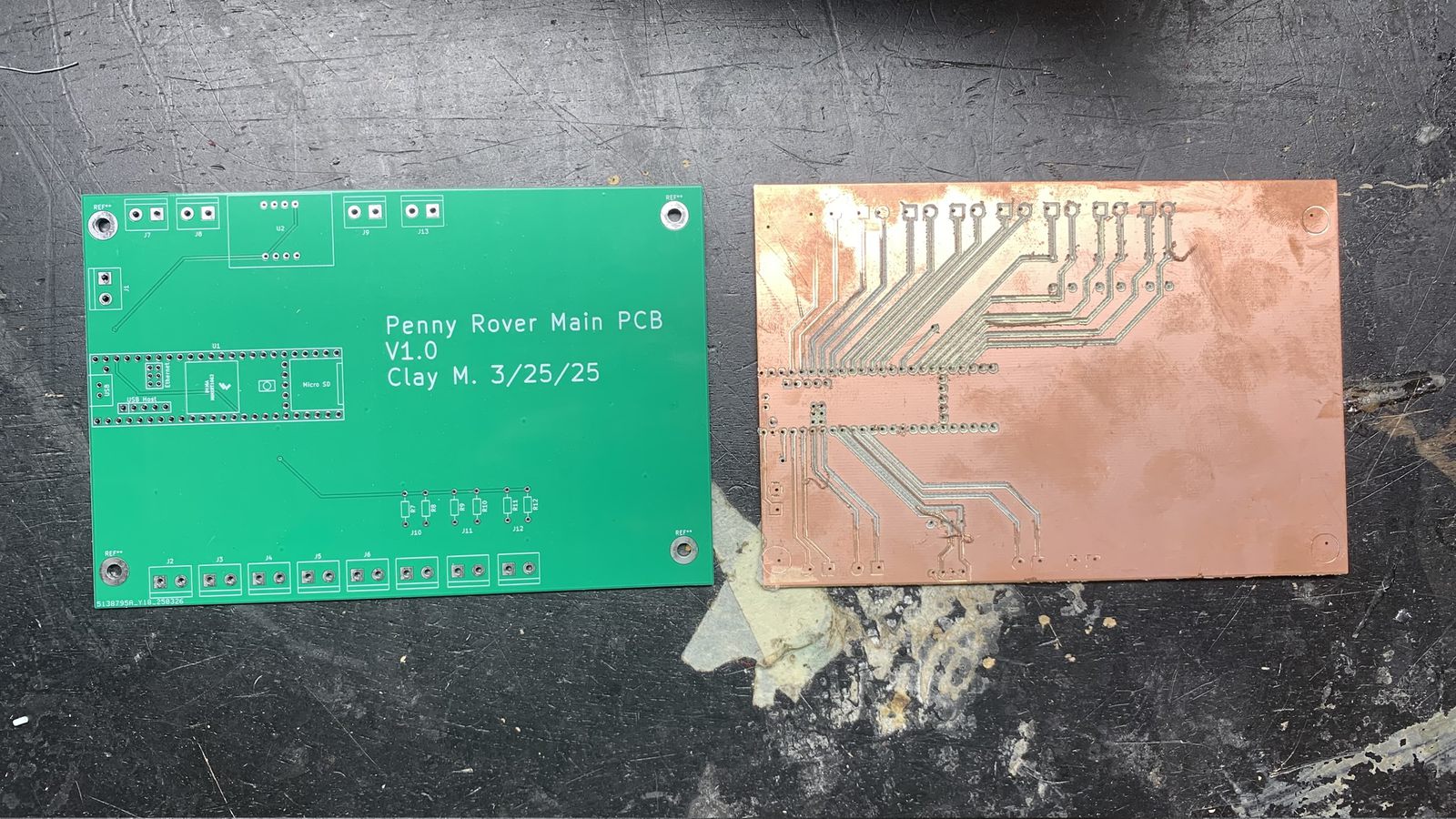
Custom PCBs I made for this project. At first I tried to engrave it on my CNC router from a double sided copper blank, but it didn't work very well so I had my design made by a vendor.
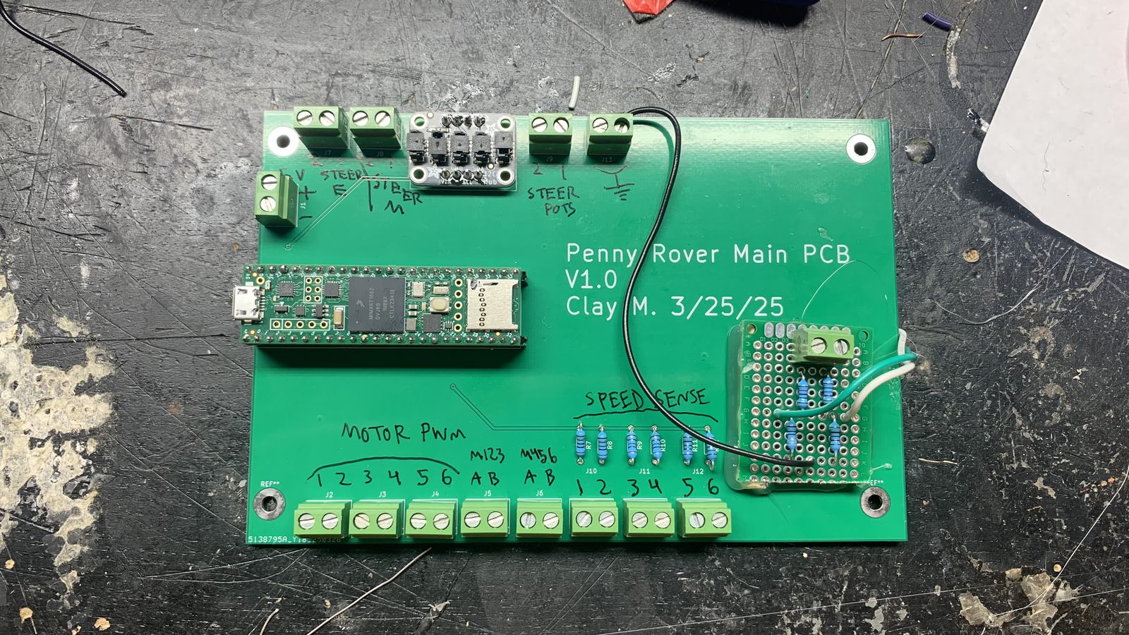
The populated PCB. The daughterboard was an afterthought. It's a couple voltage dividers for the battery current/voltage sensing to be scaled down to 3v3 for the Teensy's analog read. Terminal blocks for all the main motor driver connections, with pull up resistors and inputs for all the wheel speed sensors. an I2C breakout board. And the steering control connections were originally setup for the rotary cable actuators, which had a potentiometer and a brushed motor controller for each one. I ended up only needing a single PWM output for each linear steering actuator (functions like servos) but I could use the same terminal blocks without redoing the PCB; just a software change to run those pins as PWM servo outputs.

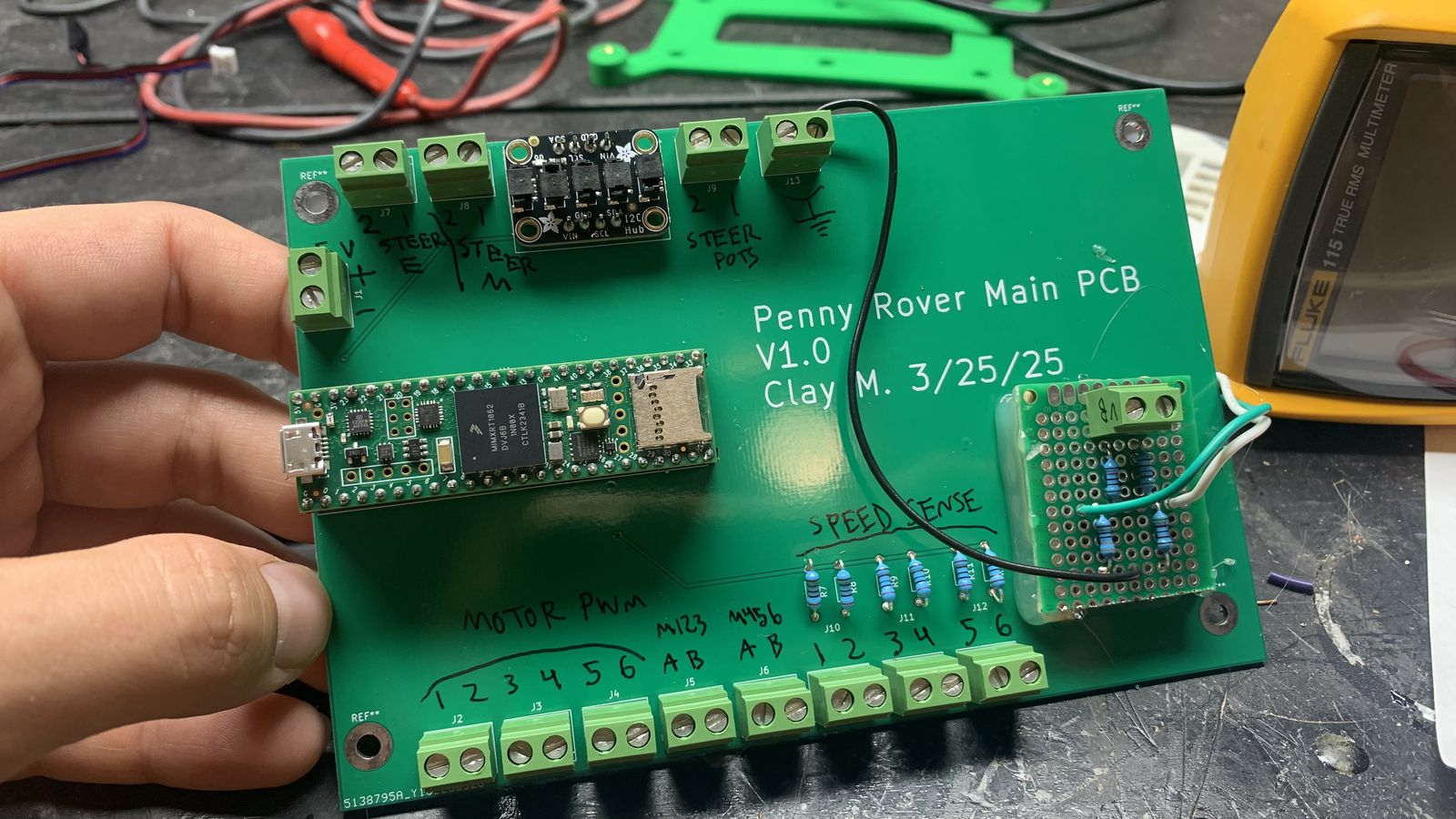
some details on the PCB and the modifications I did to it after it was manufactured.
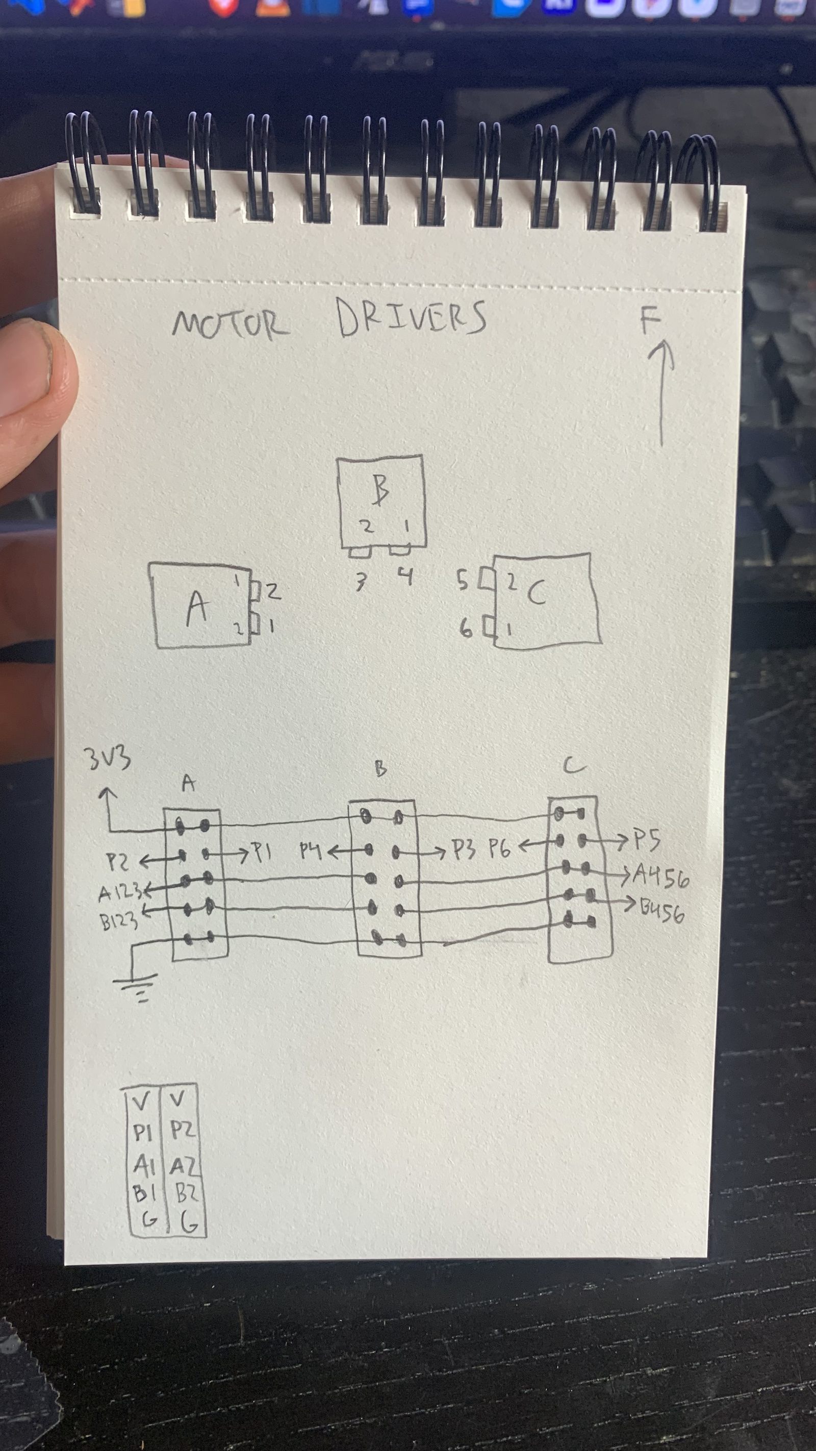
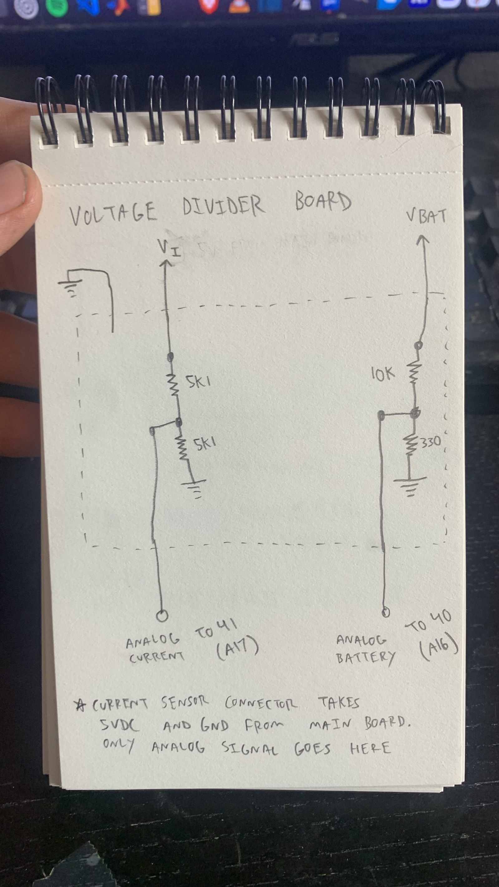
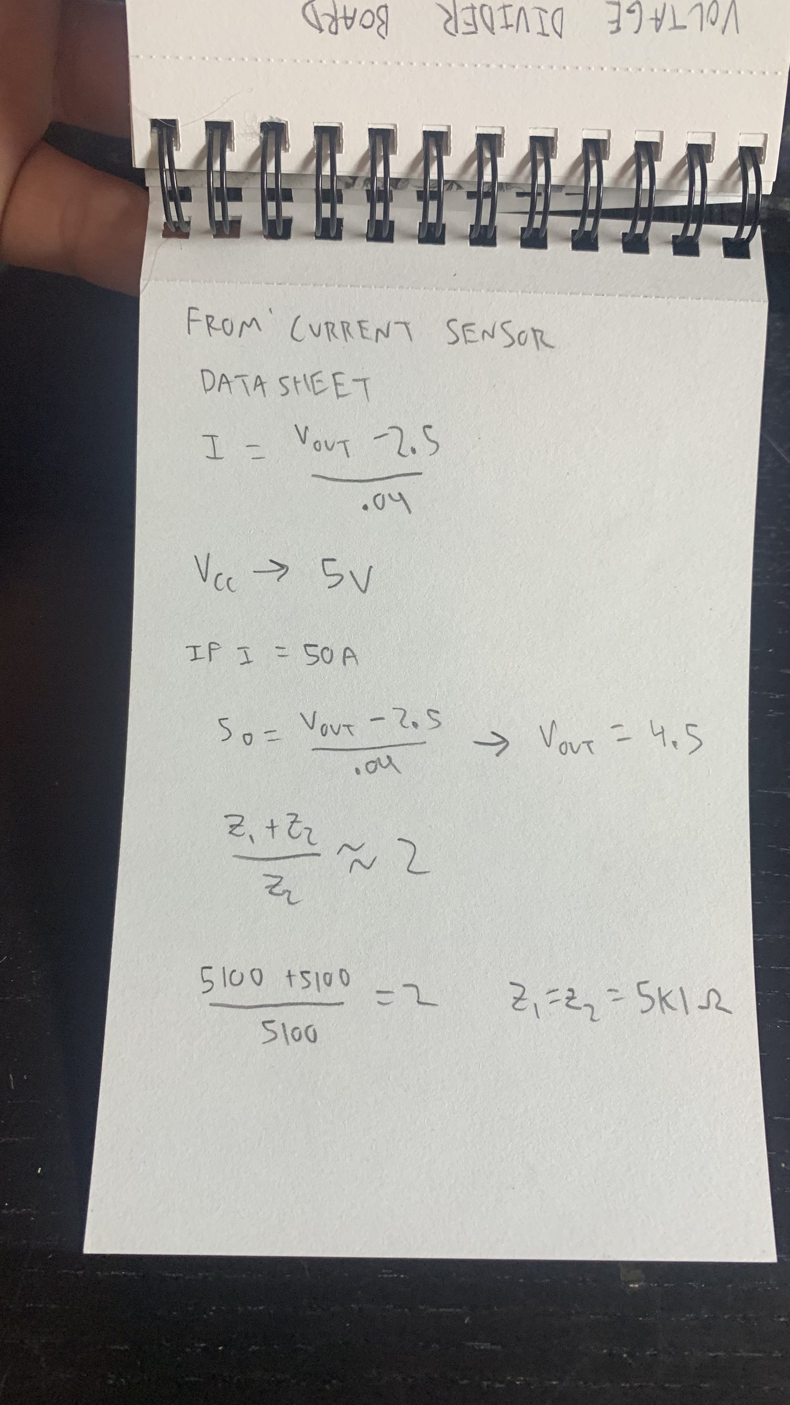
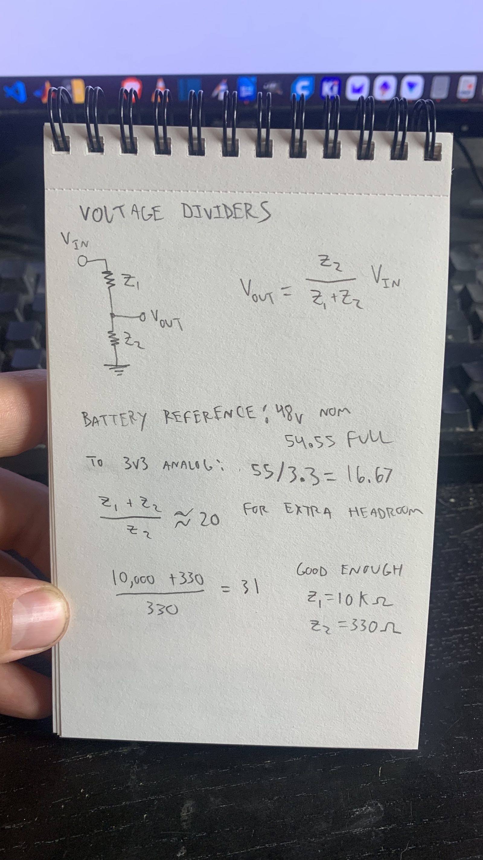
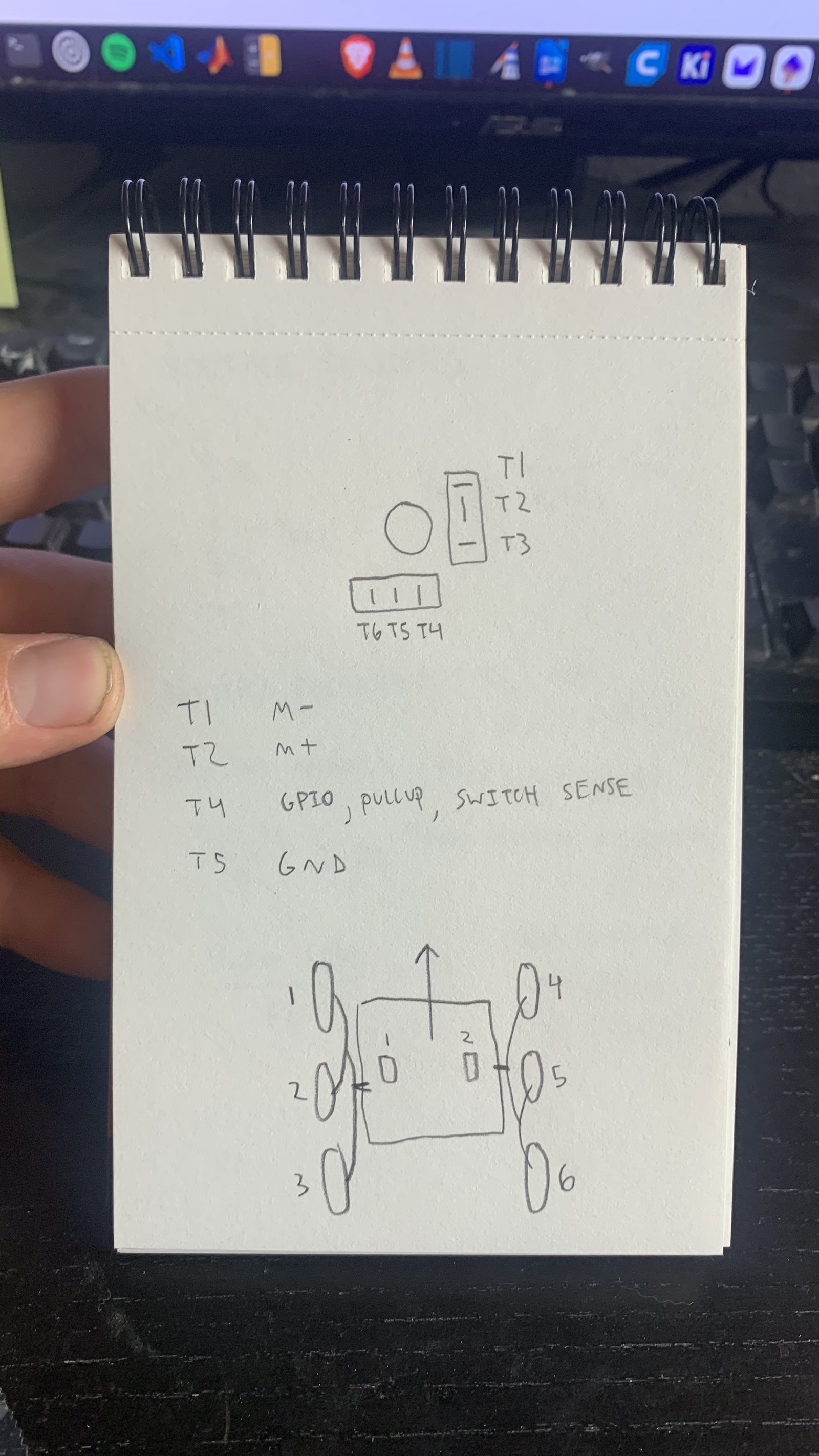
Some miscellaneous hand drawn pinout diagrams and voltage divider calculations. This is basically all the important stuff that the PCB connects to.
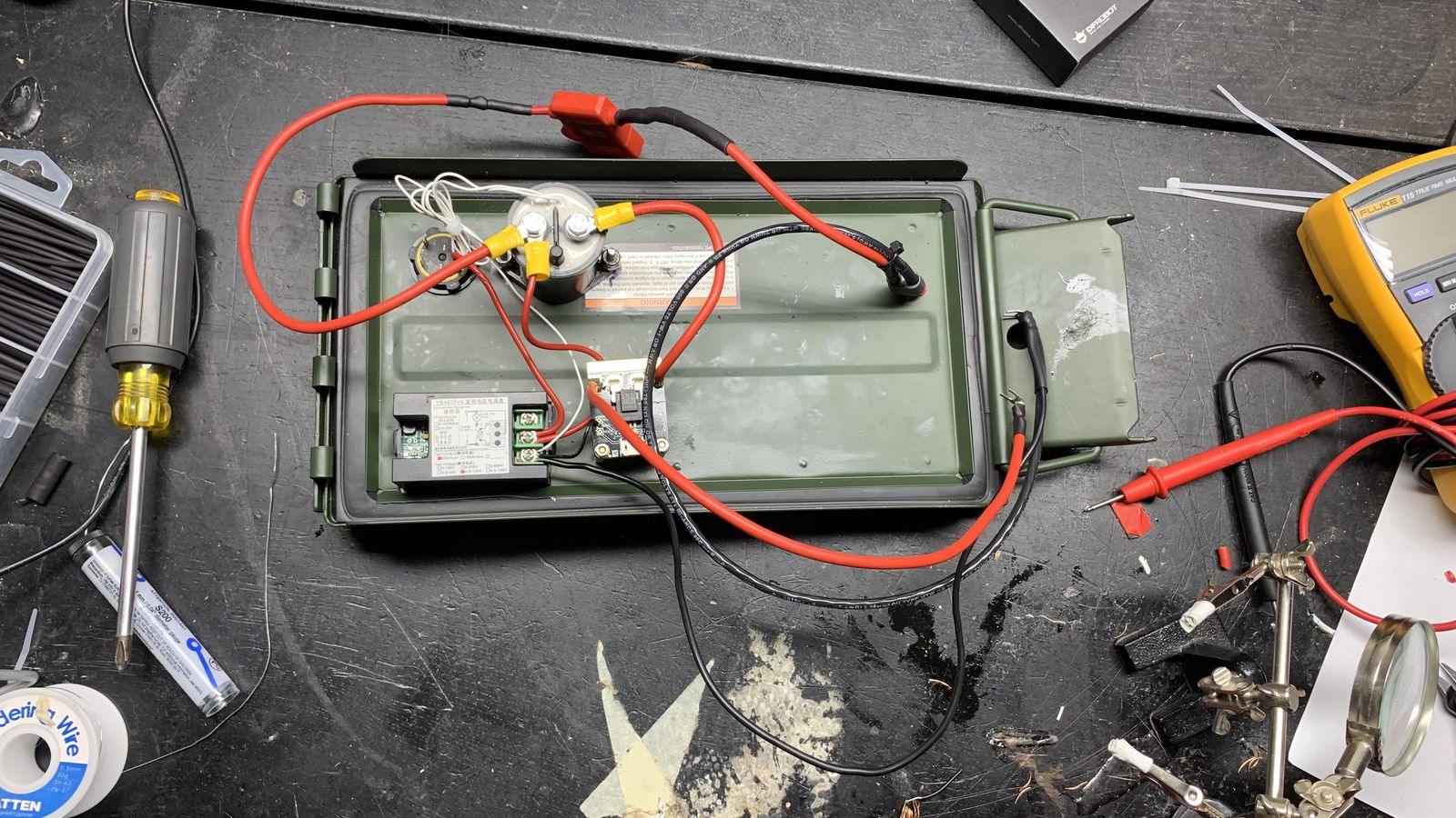
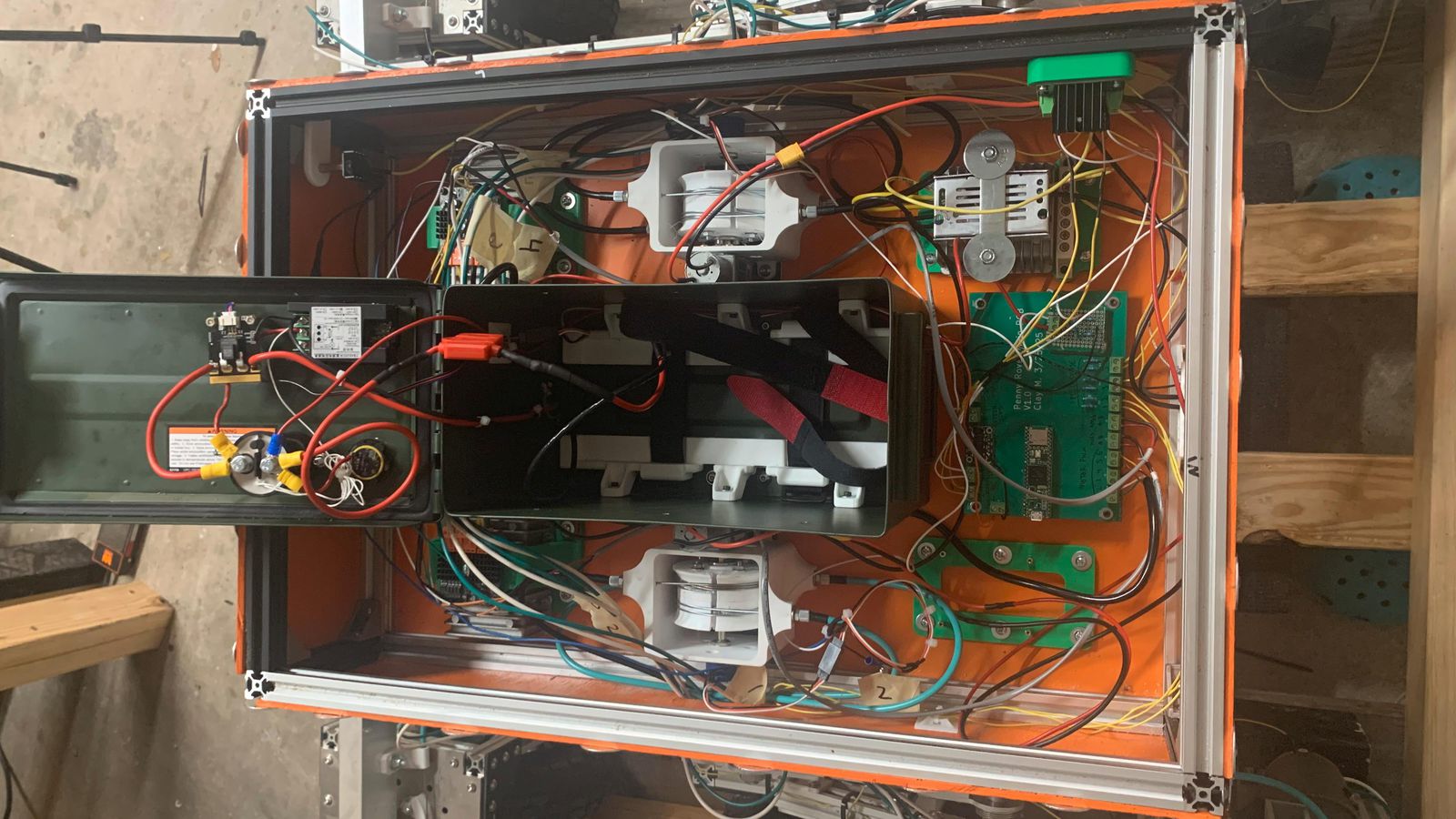
The inside of the battery box where the battery control electronics are mounted. An emergency stop button switches main battery power through a contactor. An inline fuse comes right off the battery positive terminal. A display shows the voltage visible from the outside of the lid. A current measurement module provides an analog signal to the microcontroller, and a battery voltage reference goes out through a voltage divider to the microcontroller.
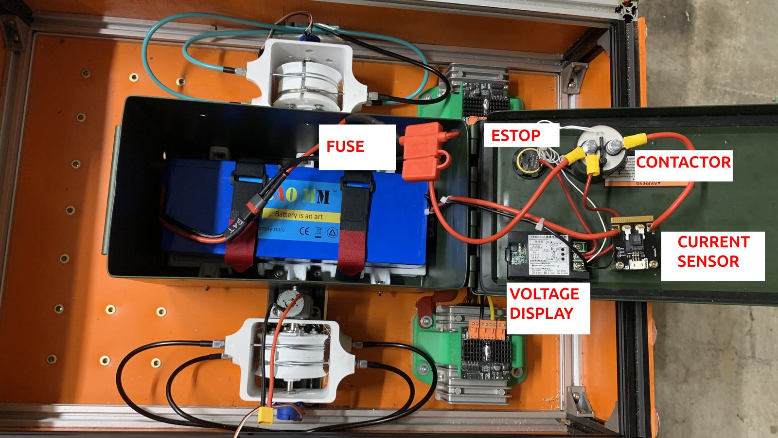
This image shows all the components of the battery system after I installed it in the vehicle.
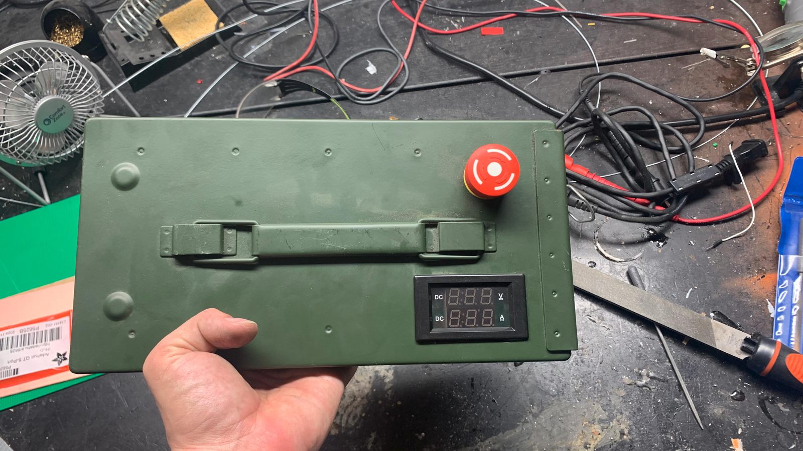
The outside of the battery top
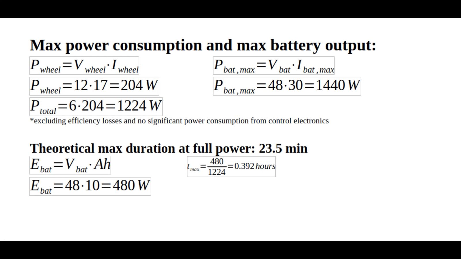
I calculated the theoretical max battery duration at my predicted max current draw at full motor power. It lasted about twice as long as this on the real test because it wasn't operating near the stall torque of the motors, where the max current measurement was taken.
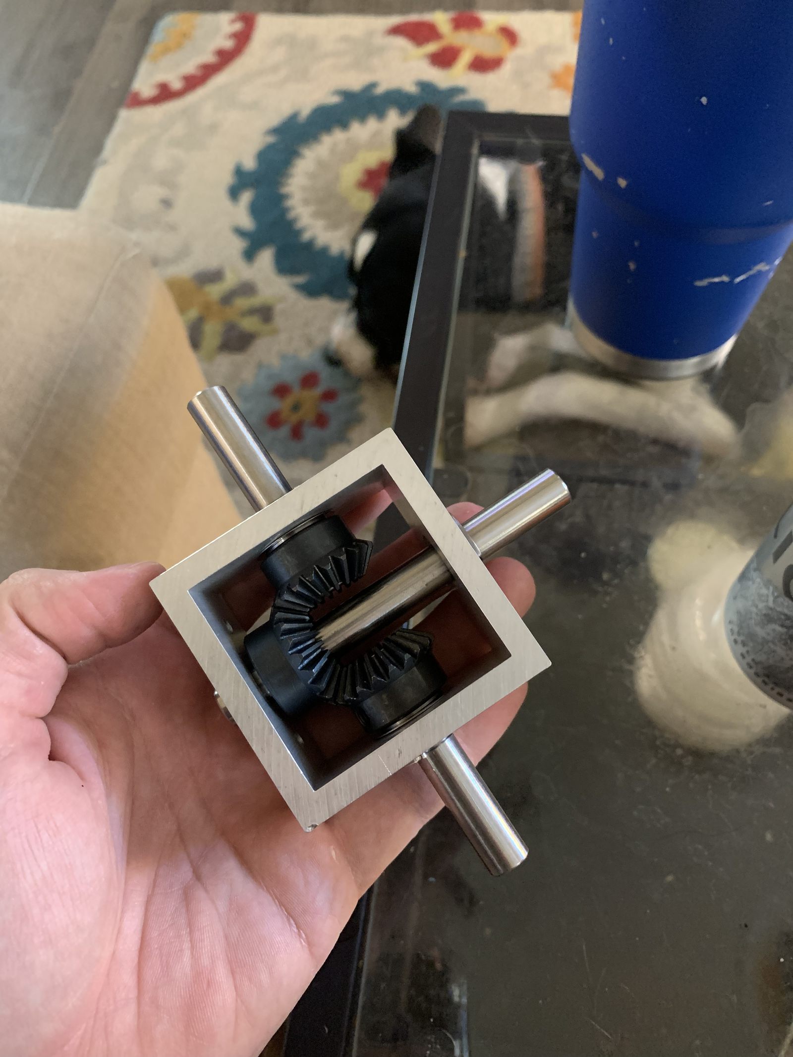
I used this off the shelf gearbox as my differential for the two halves of the rocker bogie system. The differential averages the pitch angle between both rockers, keeping the chassis at half the inclination of whichever side is articulating. This keeps all six wheels grounded and maintains stability on uneven terrain by decoupling the body's pitch from individual rocker travel. Without it, any obstacle lifting one side would pitch the entire chassis and potentially lift wheels off the ground.
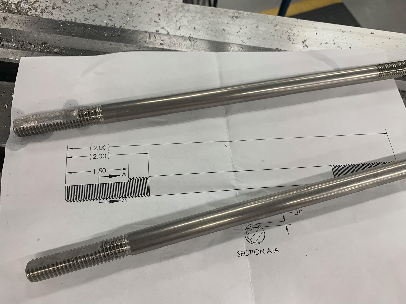
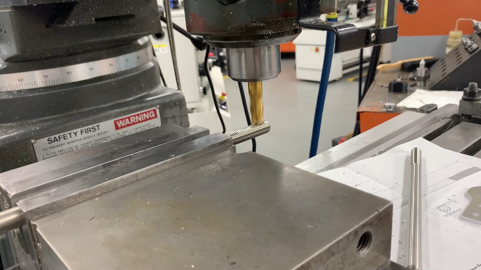
The main suspension shafts started as off the shelf precision ground connecting rods with two threaded ends. I used a die to extend the threaded length, then milled a flat to constrain the rocker arms to the end of the shafts.
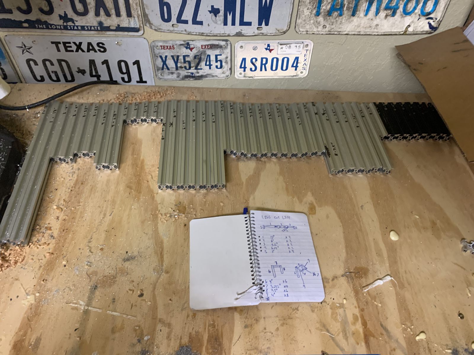
All the different cut lengths of 2020 extrusion to build the legs. Different colors and a few extra holes because it's recycled from old projects.
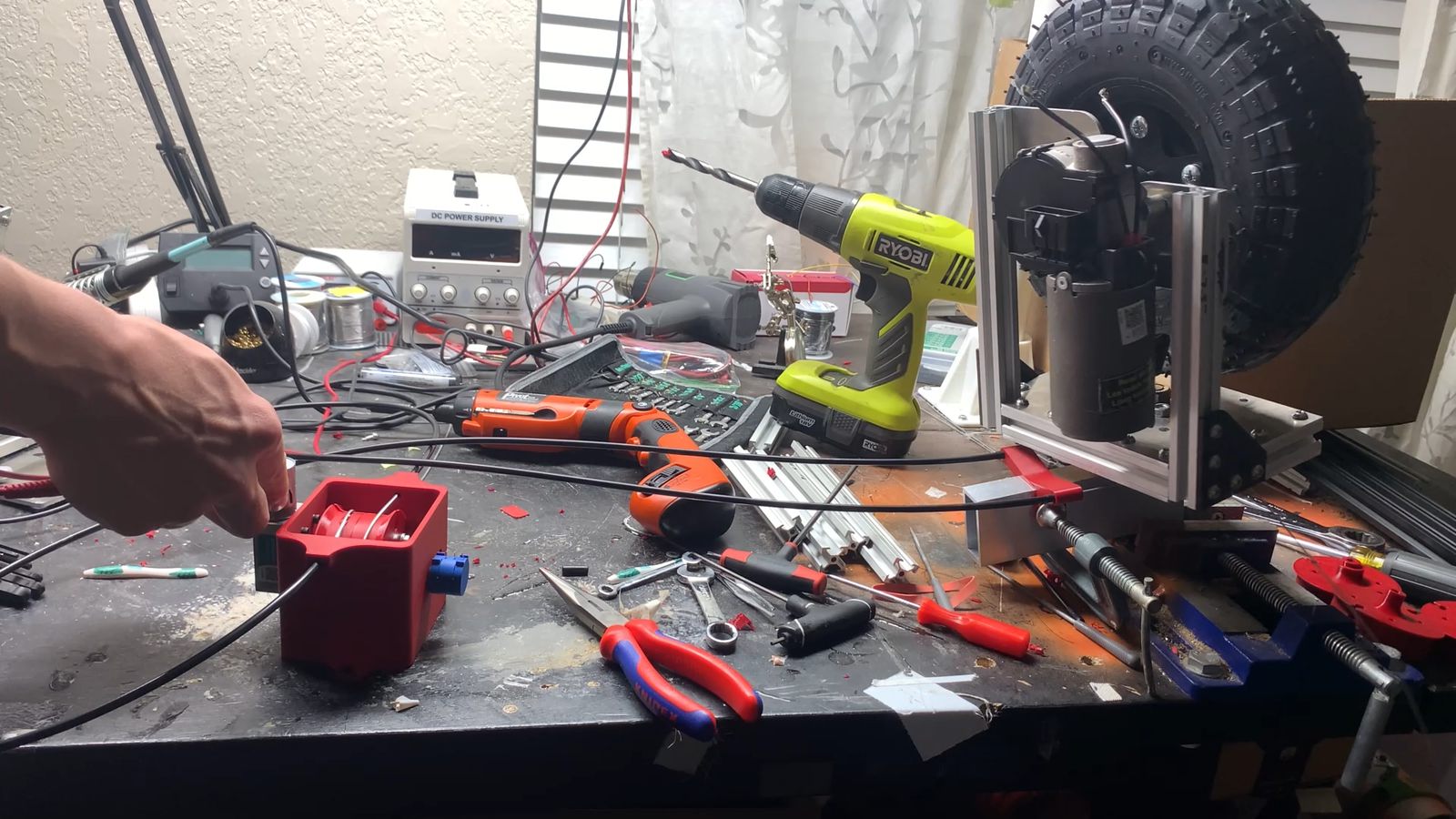
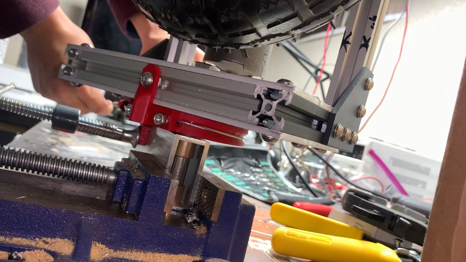
A benchtop powered steering test of a single wheel subassembly. I also did subsystem level testing for the various PID loops, traction control, etc.
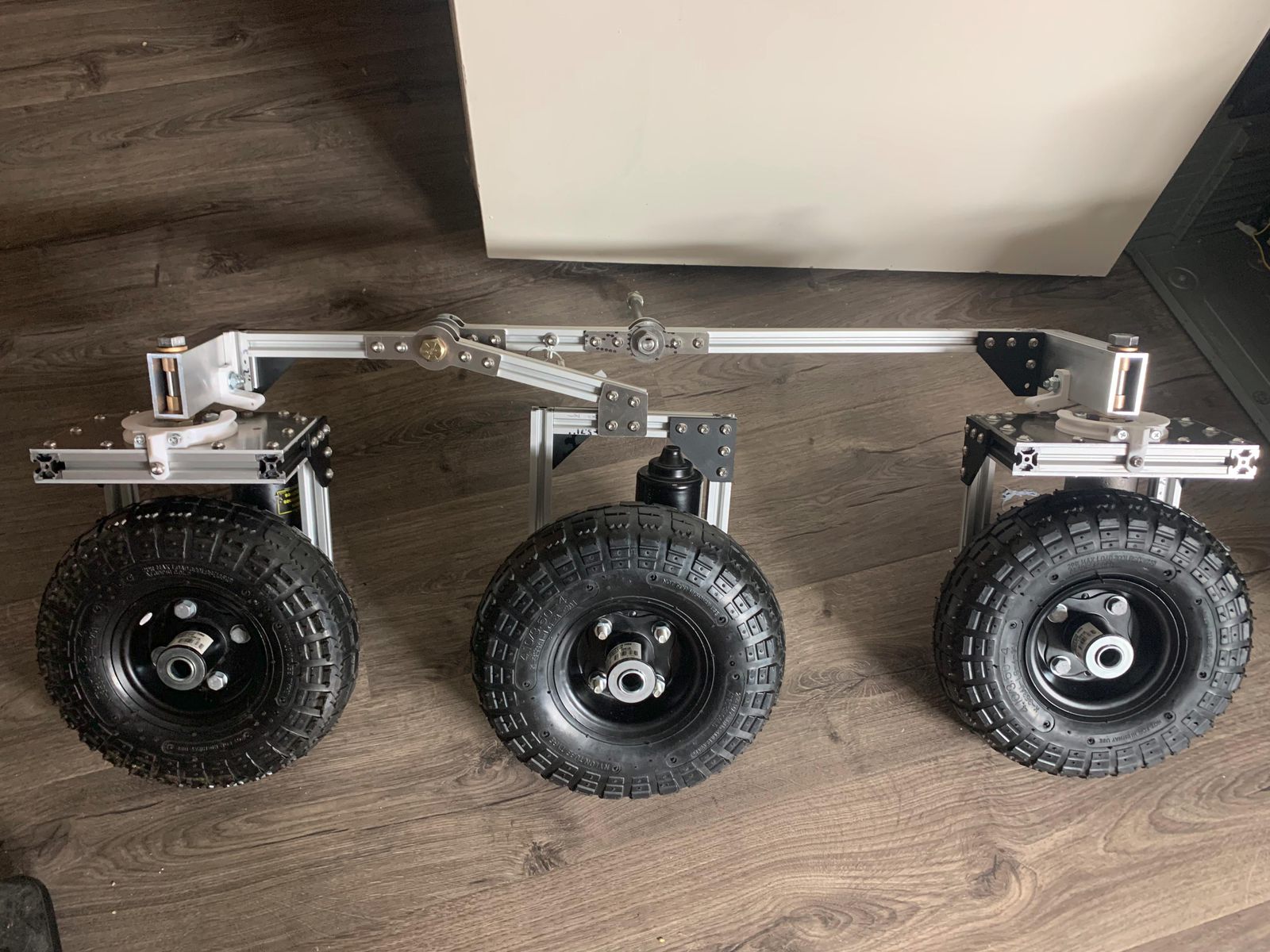
One completed leg assembly. 2020 aluminum extrusions and some custom steel sheet metal brackets. Wheels/tires are from harbor freight, bolted onto an adapter for the keyed shaft on the wiper motors. A single bolt through the center of the keyed shaft holds on each wheel. These wheels aren't meant to be driven, the bearings in the center are unloaded and doing nothing in this application. All the weight, axial and radial loads are supported by the bearings in each motor.
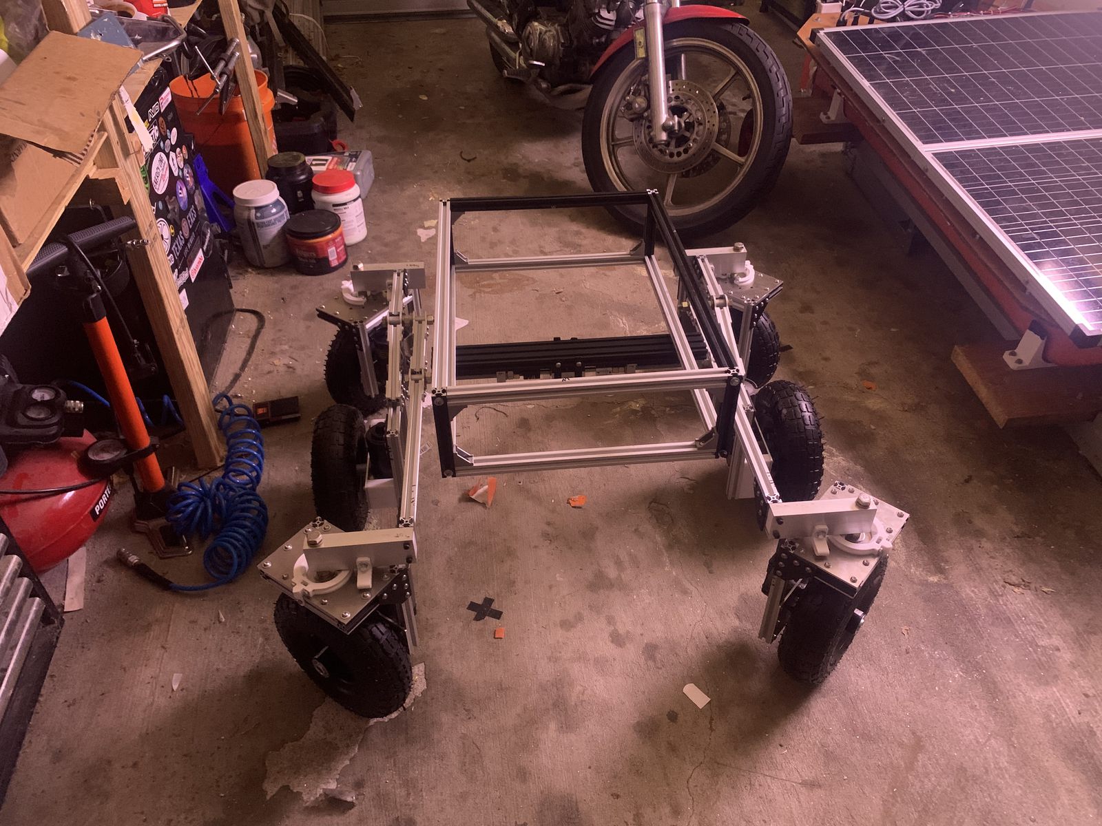
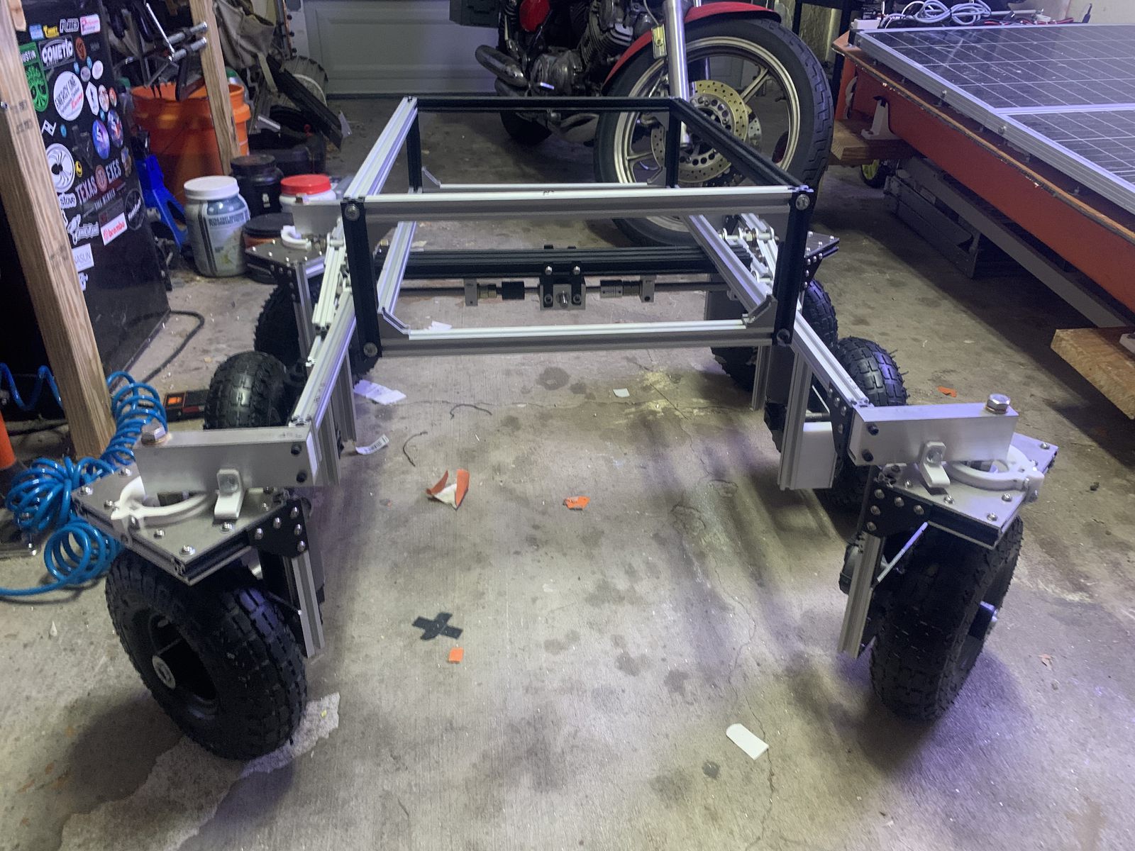
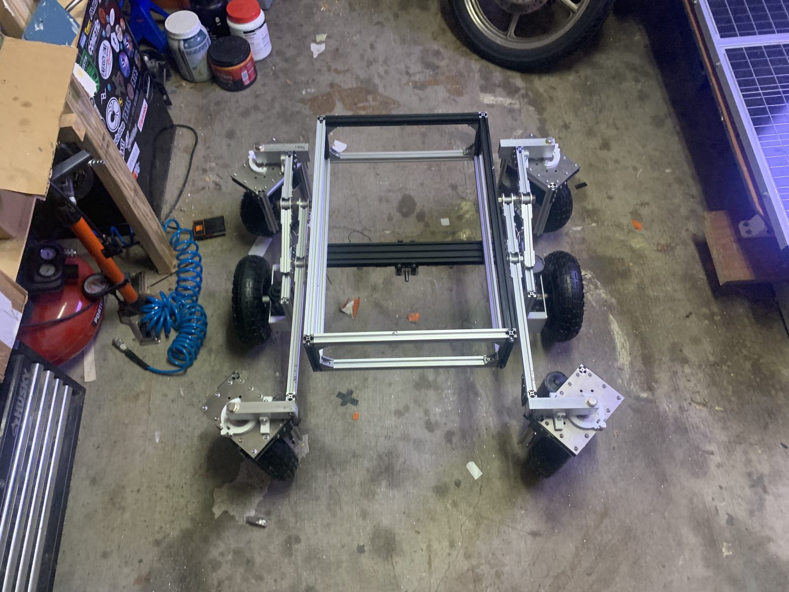
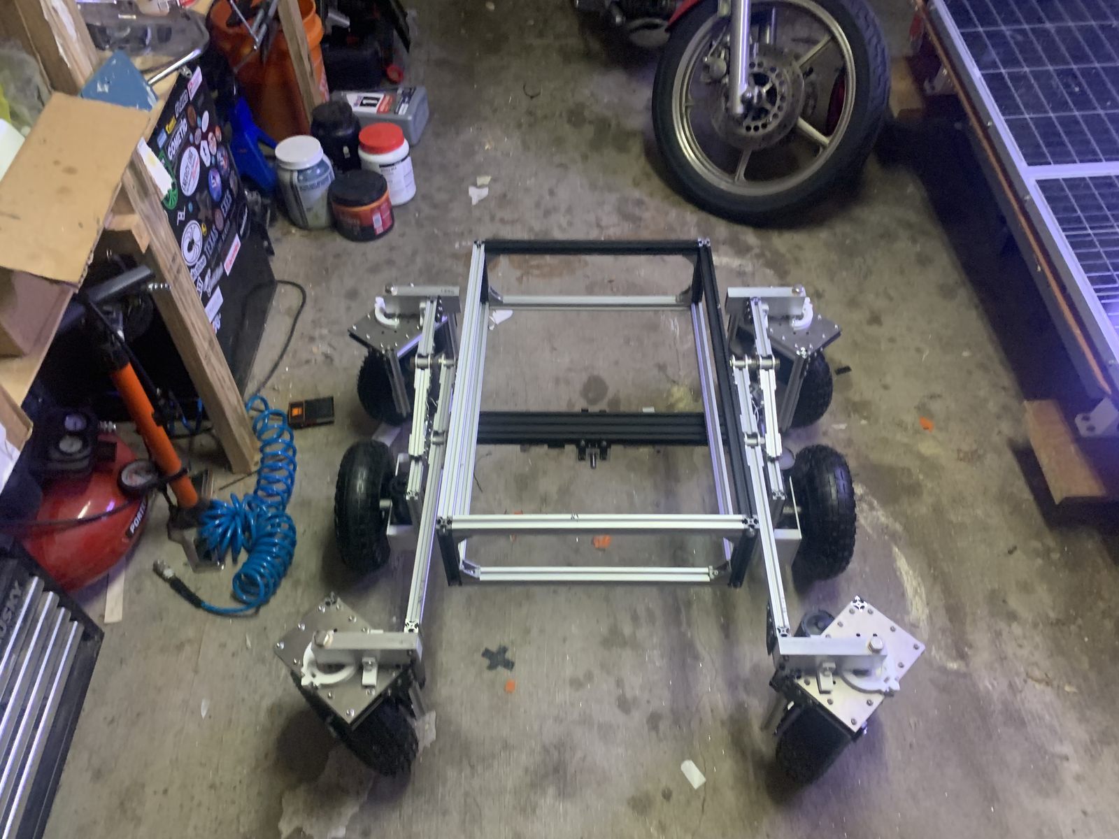
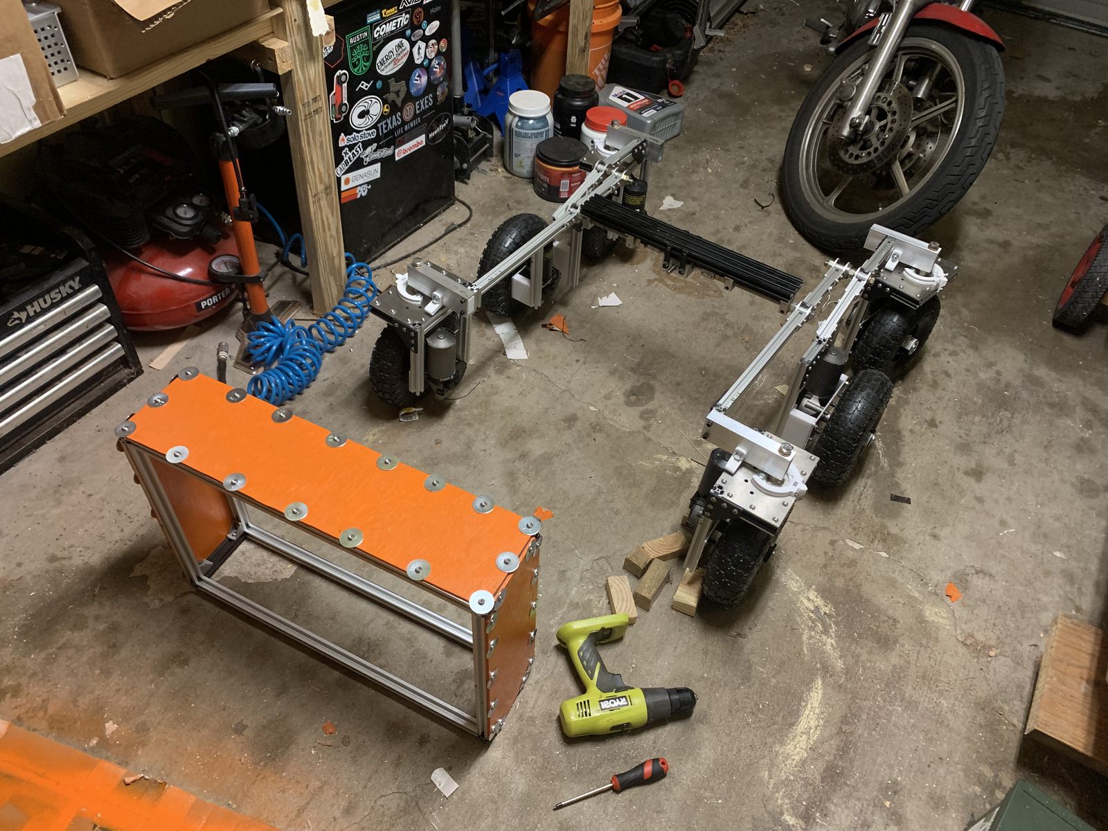
The completed suspension and body frame put together. All made out of 2020 aluminum extrusions.
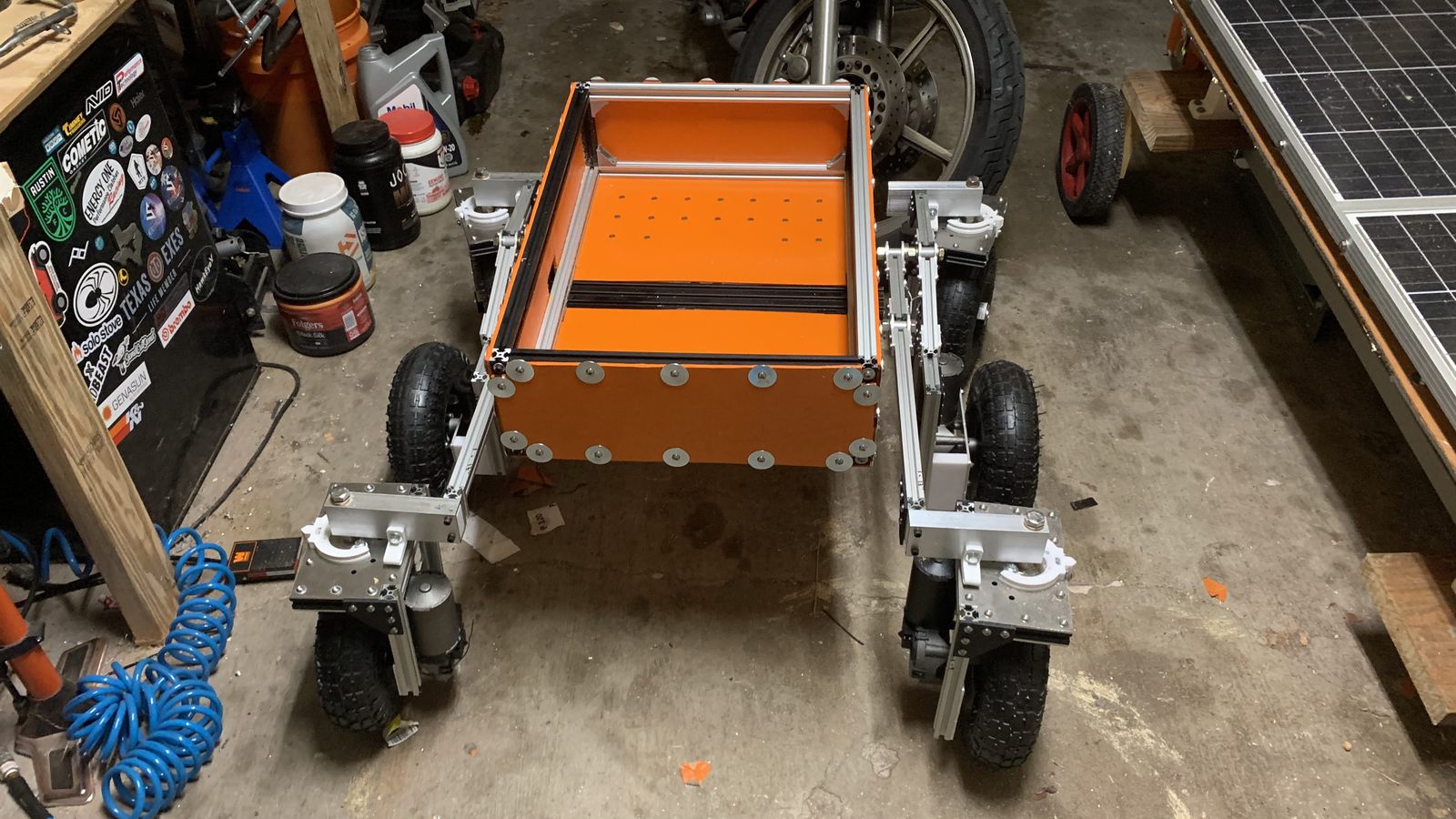
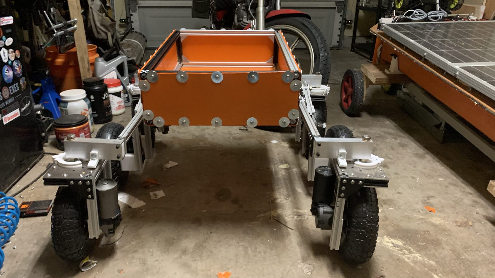
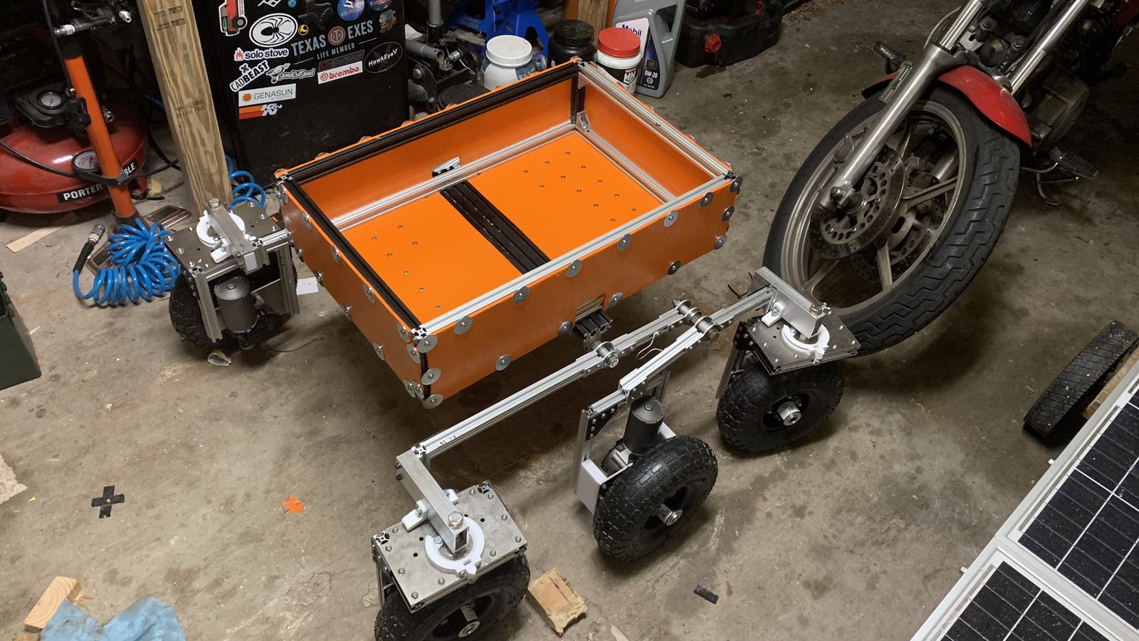
The empty body installed on the suspension. It has wooden side panels and a 2020 aluminum extrusion frame. The bottom panel is polycarbonate, with rivet nuts installed on a grid for bolting down the electronics in a modular and rearrangeable way.
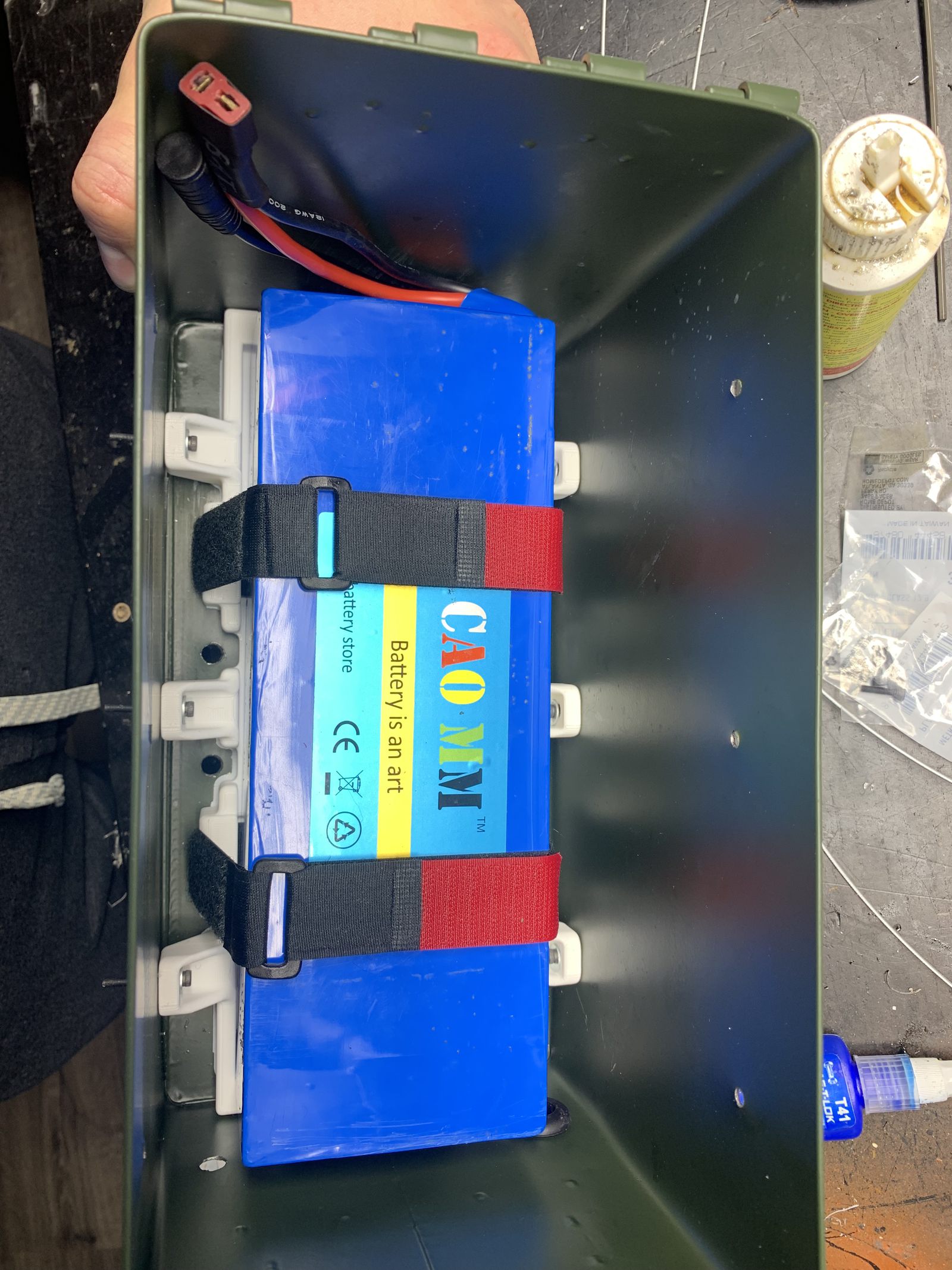
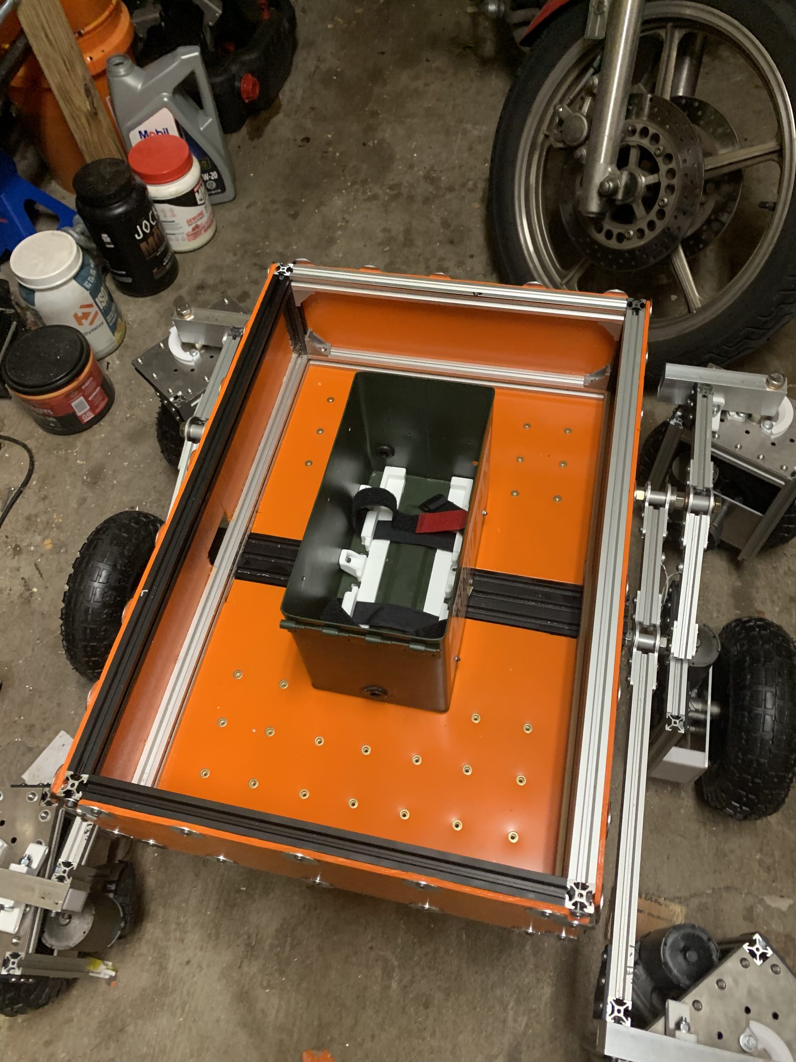
This battery box mounted centrally in the body keeps the heaviest component right above the suspension pivot point. The COG is kept in the middle so it doesn't tend to sag to one side, and a minimal moment of inertia prevents too much stress on the differential gears when the vehicle drops over a sudden bump and the body wants to rotate.
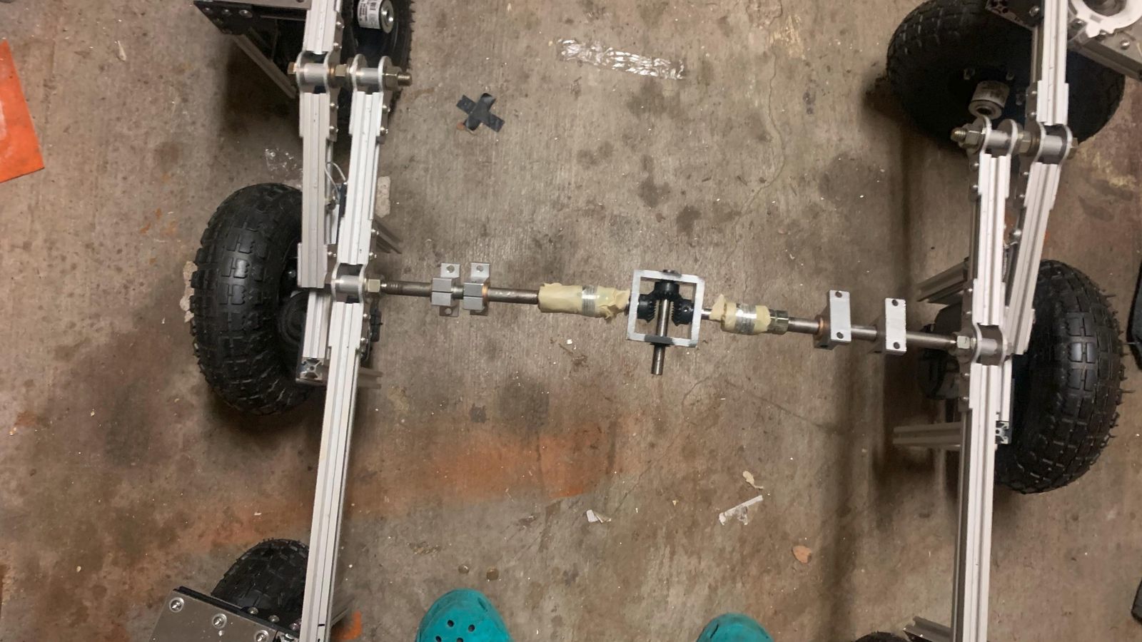
The skeleton of the suspension with the old couplers before I replaced them. This gearbox in the middle is a differential which replaces the typical bar going over the top to connect the two sides of a rocker bogie. The differential is fixed to the frame. It ensures that the body will always be at an angle halfway inbetween the two angles of each main rocker. All the other body attachment points are free spinning relative to the shafts going into this gearbox.
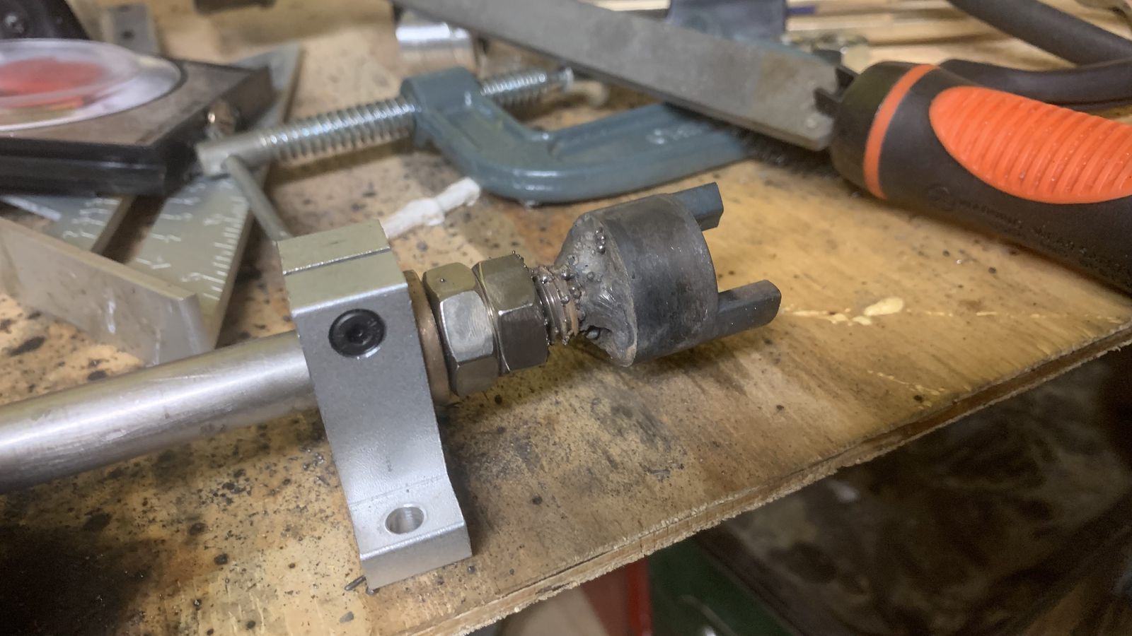
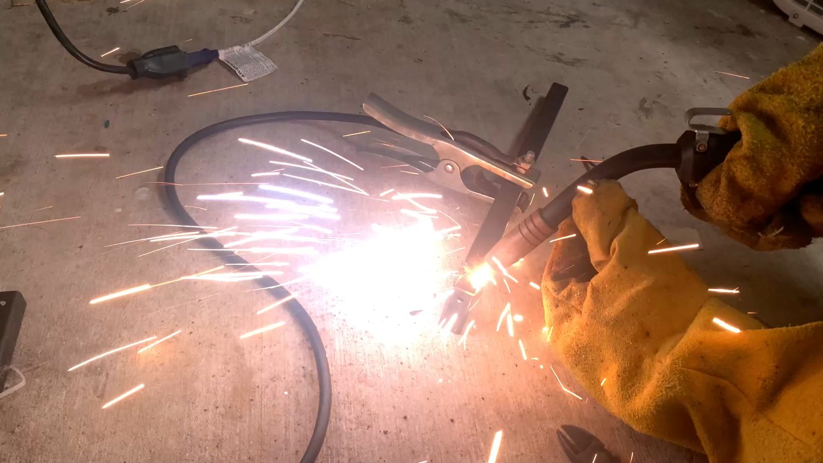
I welded these lovejoy couplers directly to the shaft to eliminate the torsional play from the flexible couplers. I'm not a talented welder, but it holds.
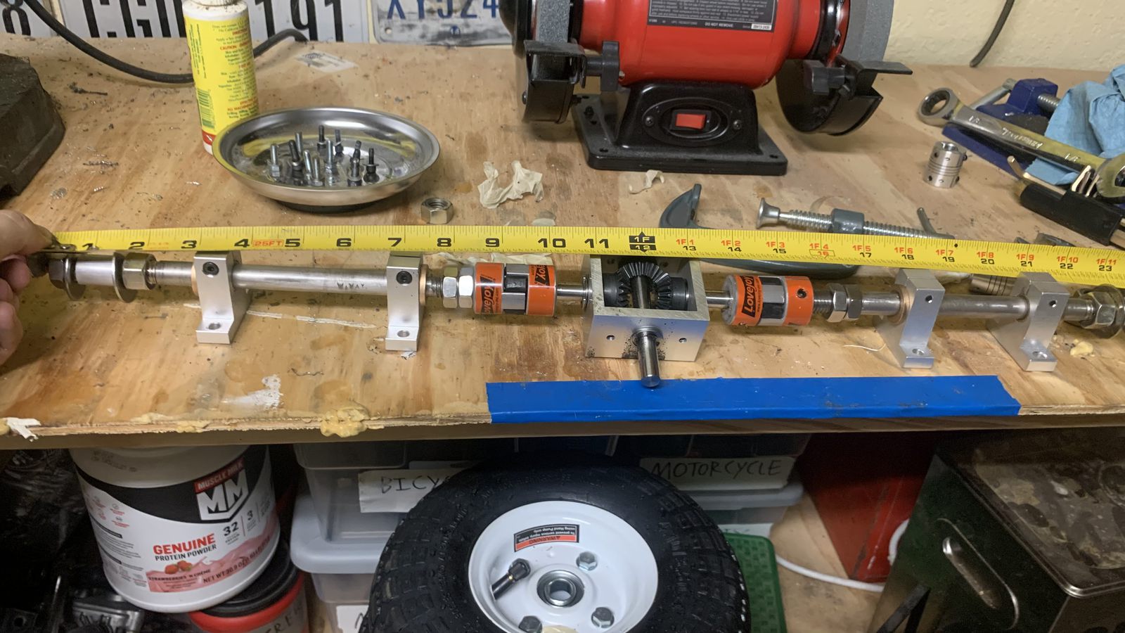
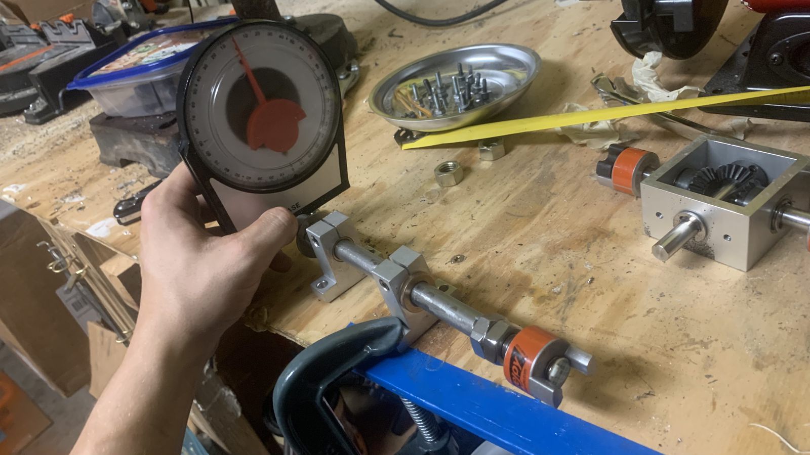
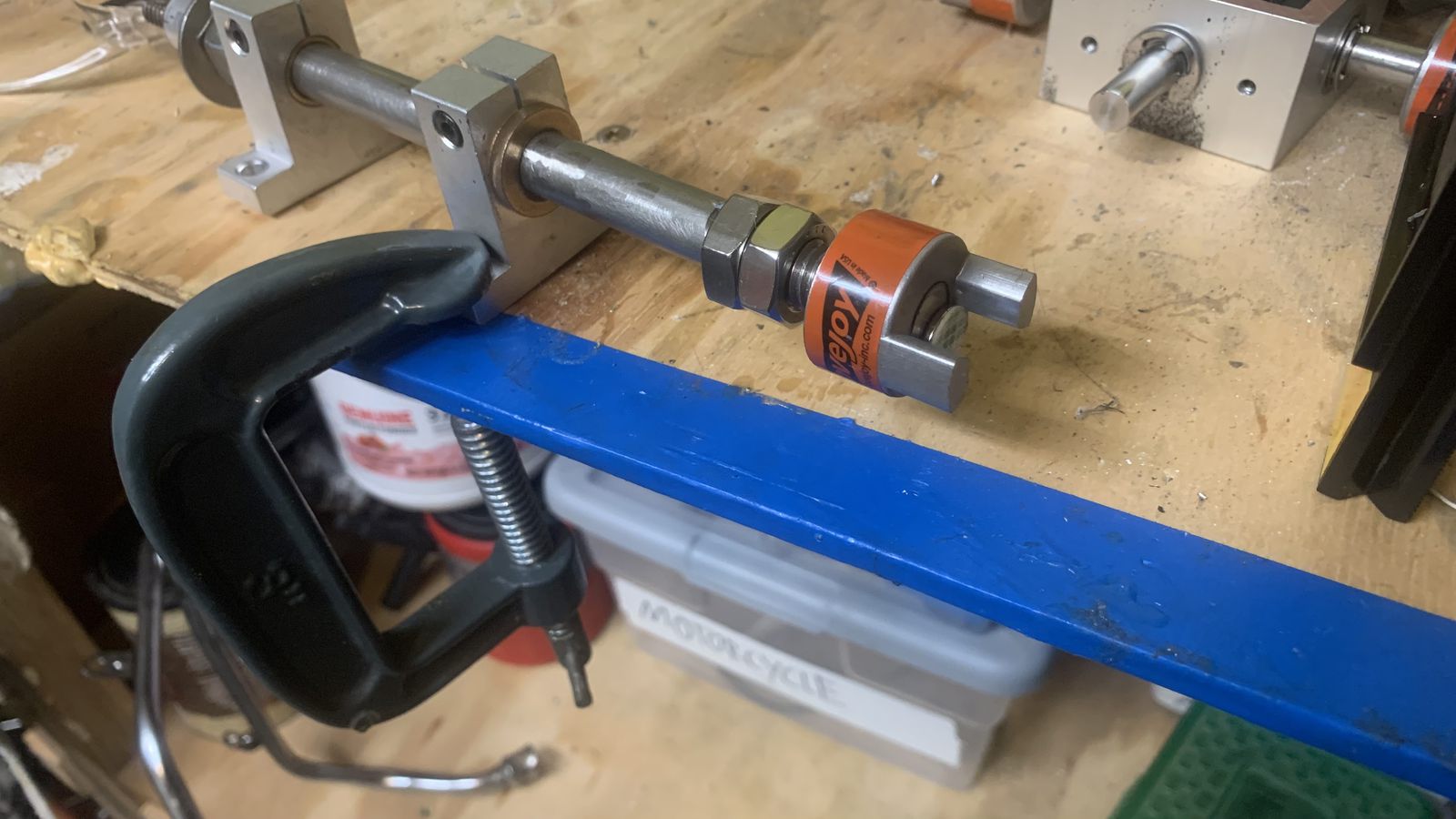
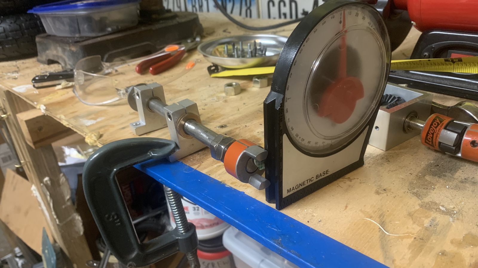
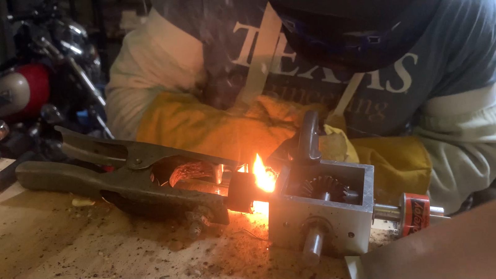
Setting up for welding on the lovejoy couplers clocked in correctly. It's still possible to disassemble because the couplers can disconnect from each other, and the bushings disconnect from the body, then the shafts can slide out the other end.
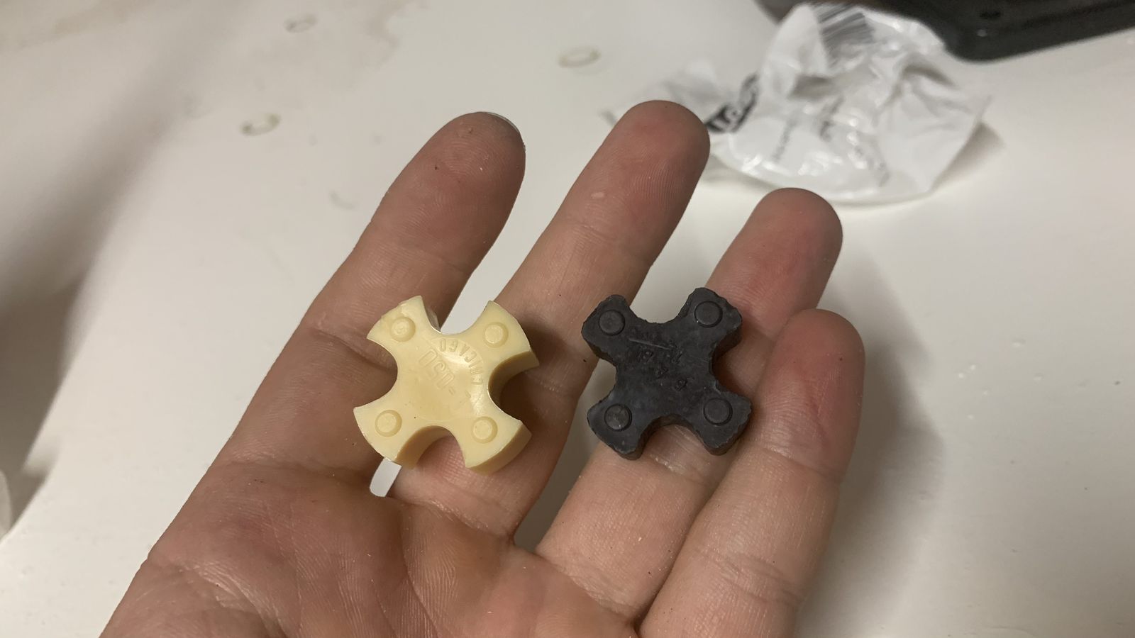
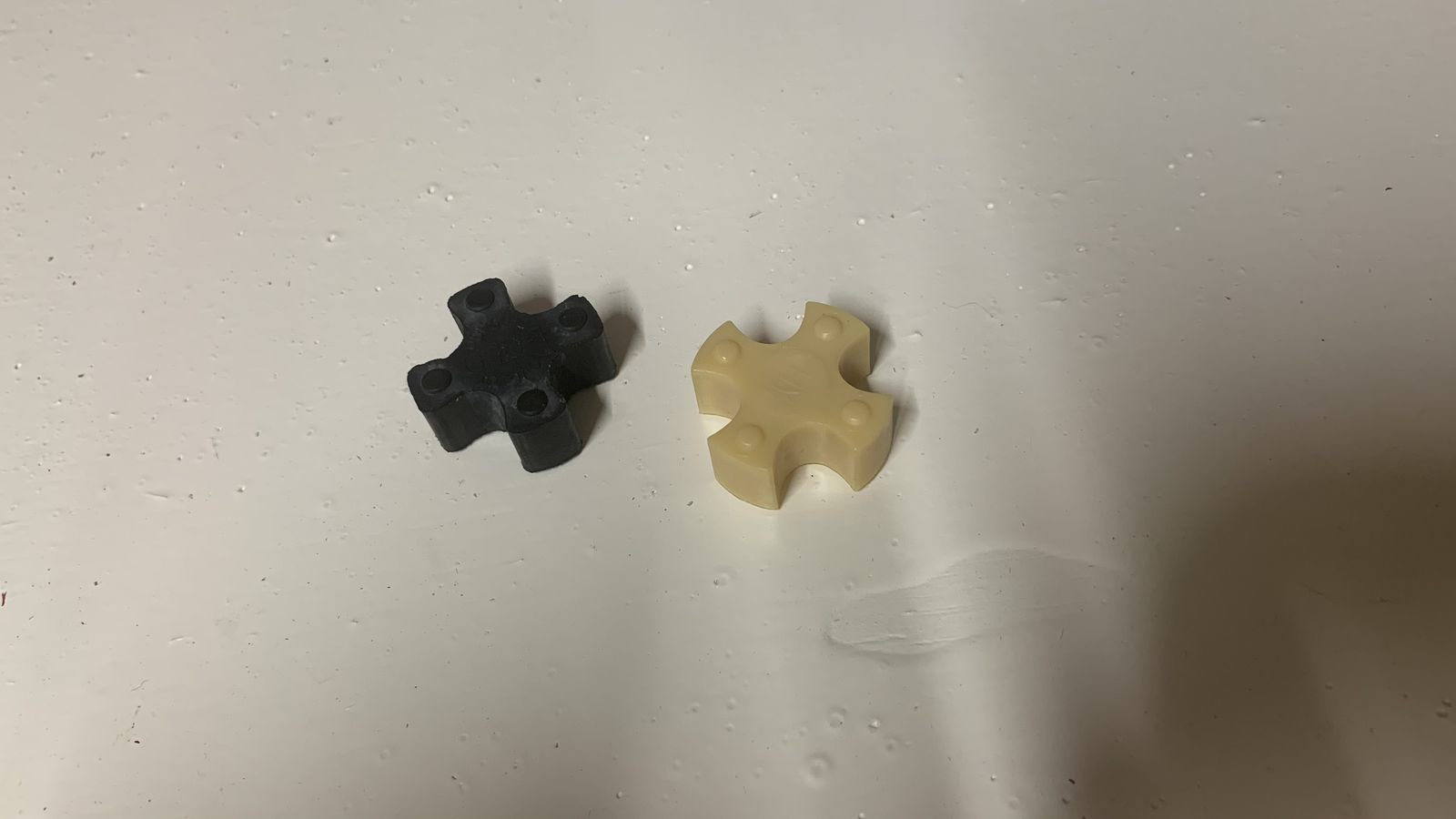
The spiders for the lovejoy couplers. I switched from the original buna-n to a harder durometer nitrile for less play.
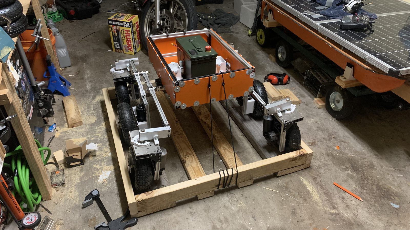
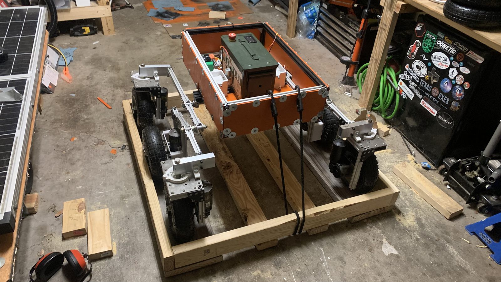
I moved halfway through this project and built this custom pallet for transportation. It later became a recovery sled to drag a dead vehicle out of the field.
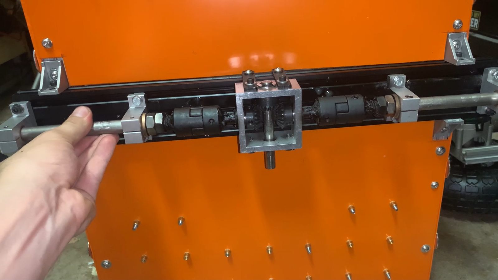
The redone differential system with welded lovejoy couplers.
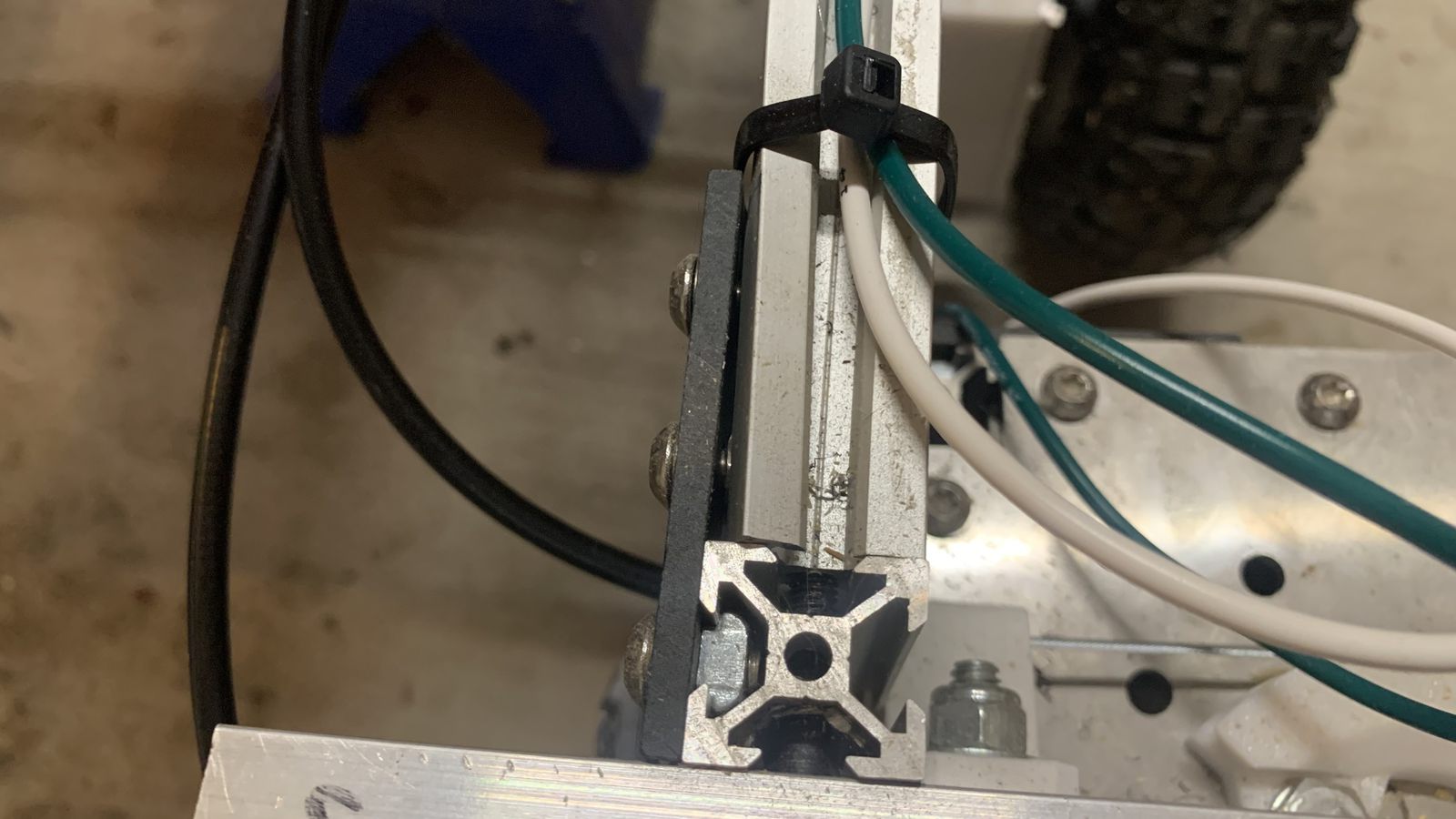
I underestimated the torsional stiffness of the aluminum extrusion arms. They were ok in pure bending supporting the vehicle's weight, but as soon as there was torsion during a turn in place maneuver they yielded badly.
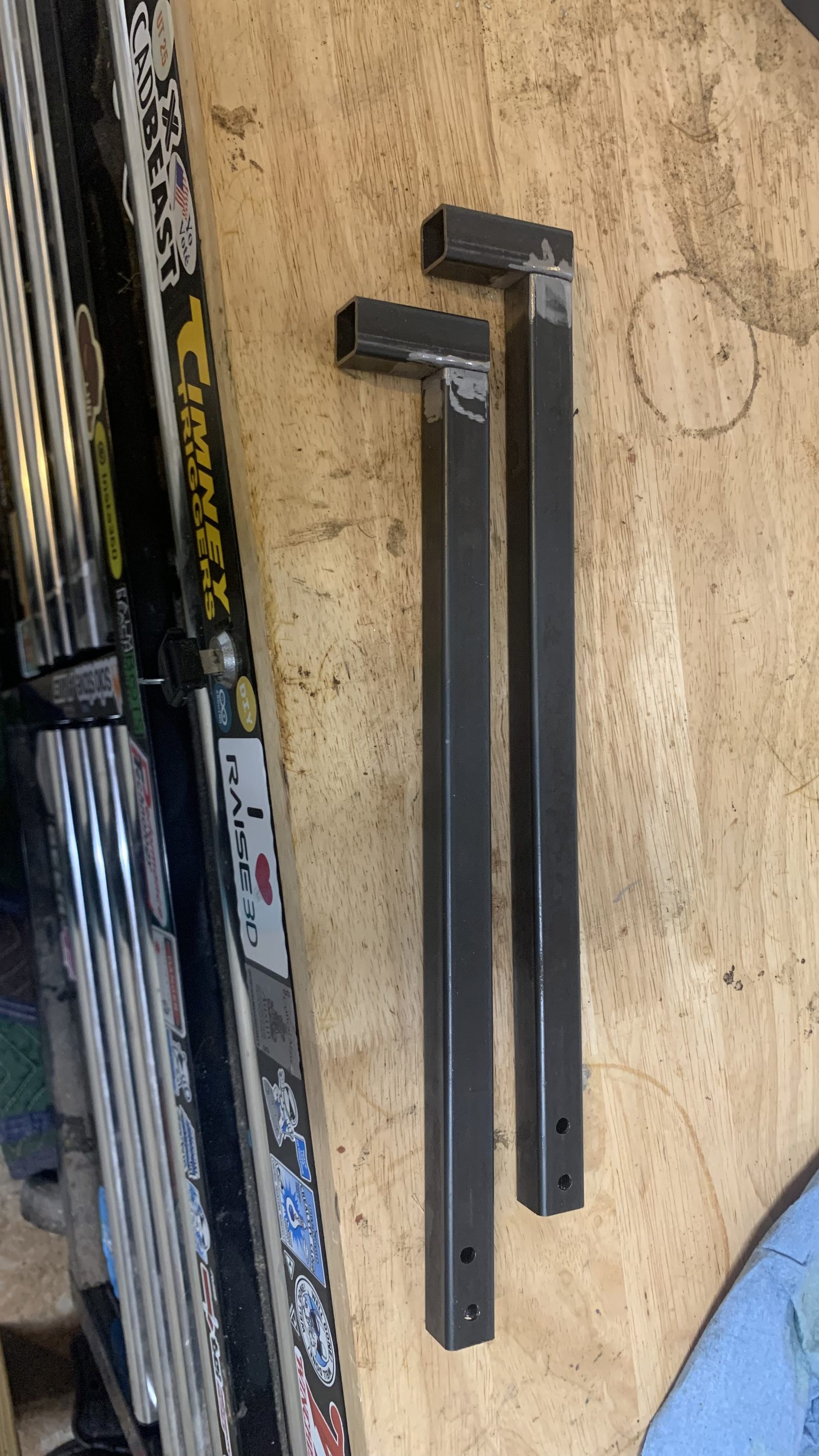
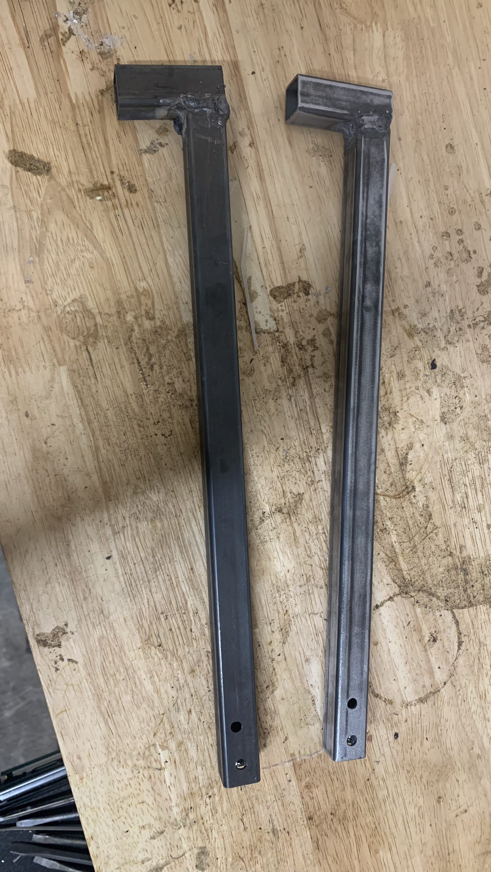
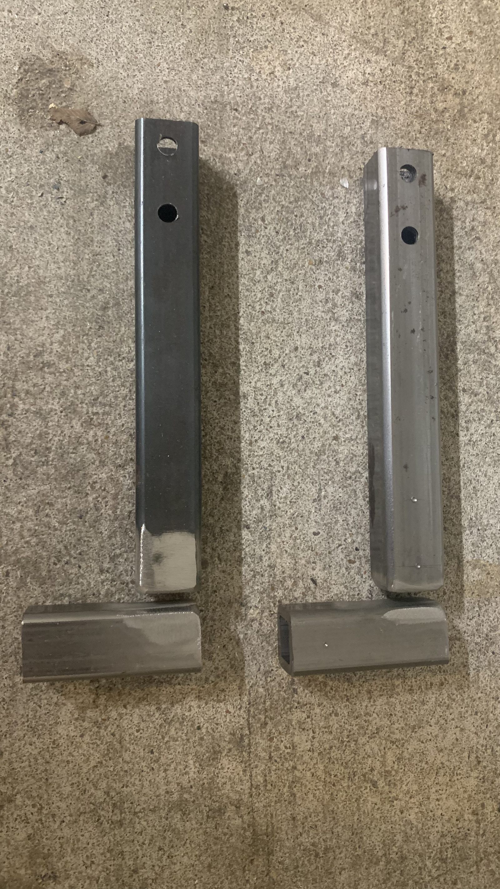
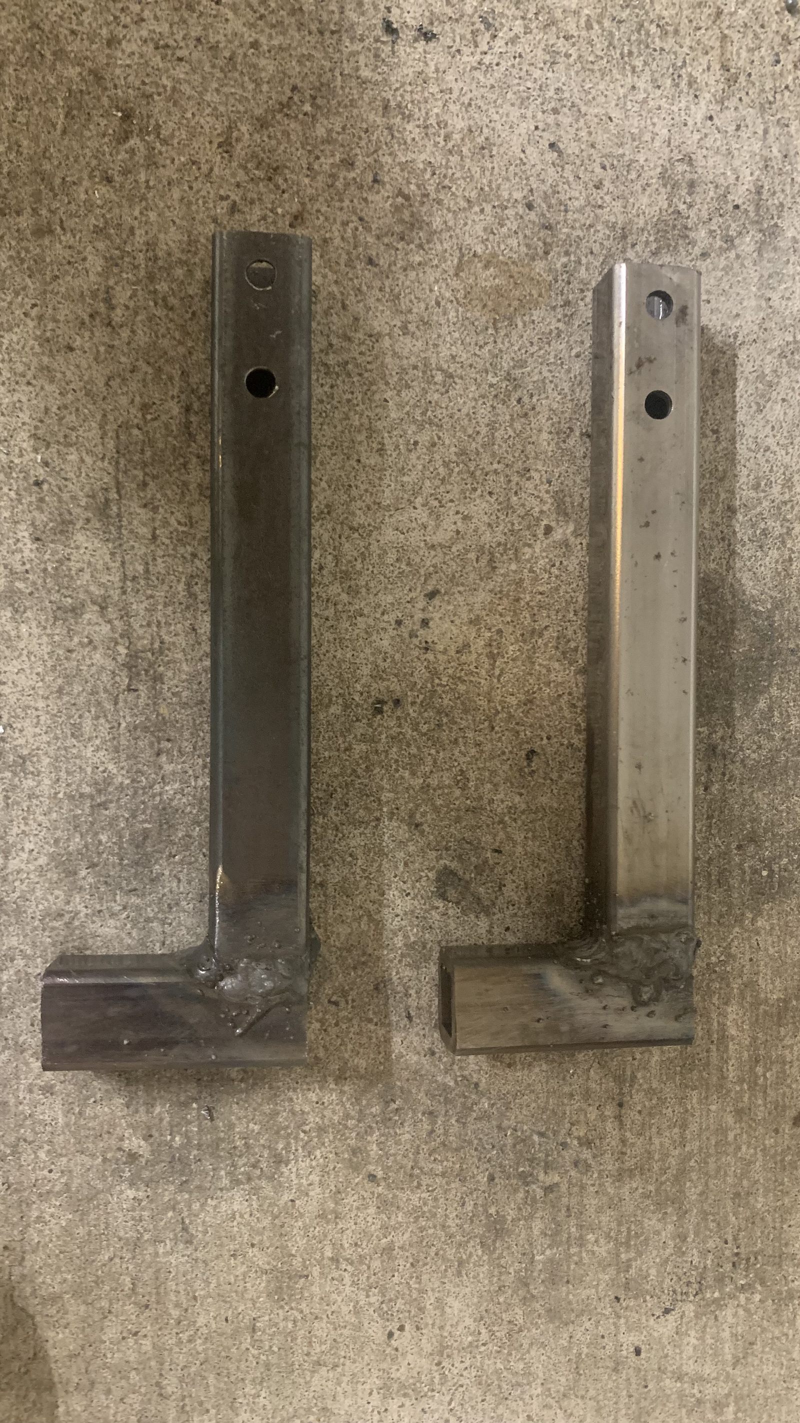
I welded some new arms out of 3/4" steel square tubing. Dimensionally close enough to be a drop in replacement once a few holes were drilled in, and far more rigid.
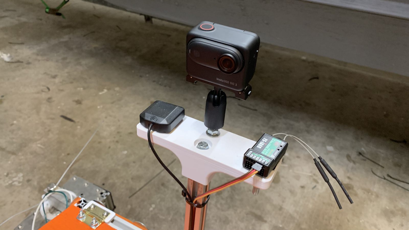
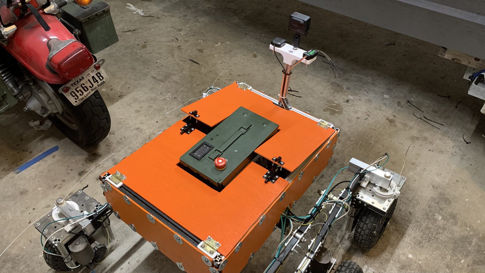
The rear mast holds an action camera, the GPS antenna, and the RC antenna
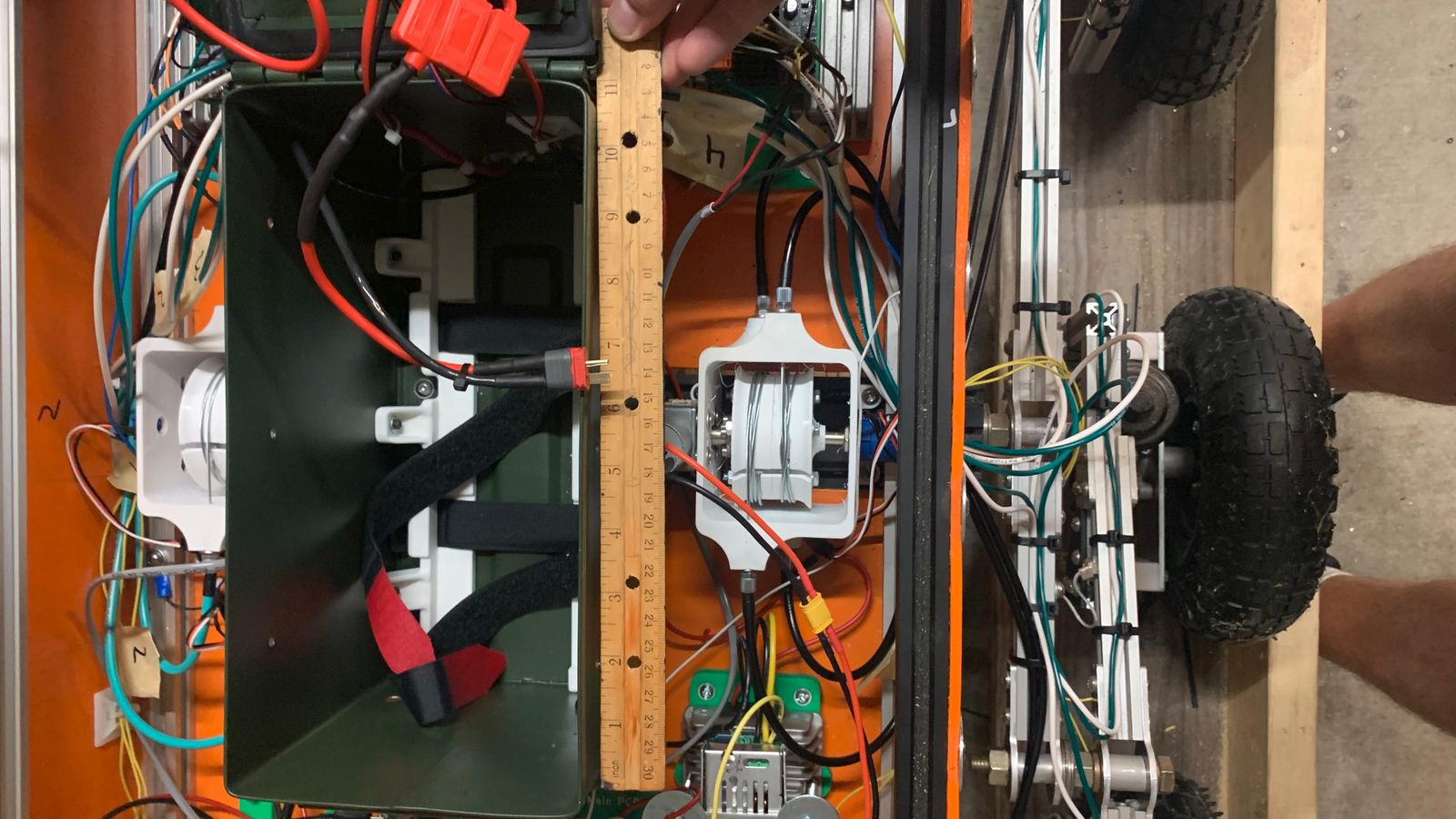
The old rotary steering cable actuators as installed. They were an interesting idea and kinda worked, but just struggled with play and lack of torque. They were a little overcomplicated and rather than continue trying to iterate and improve them, I chose to scope down and switch to an off the shelf linear actuator.
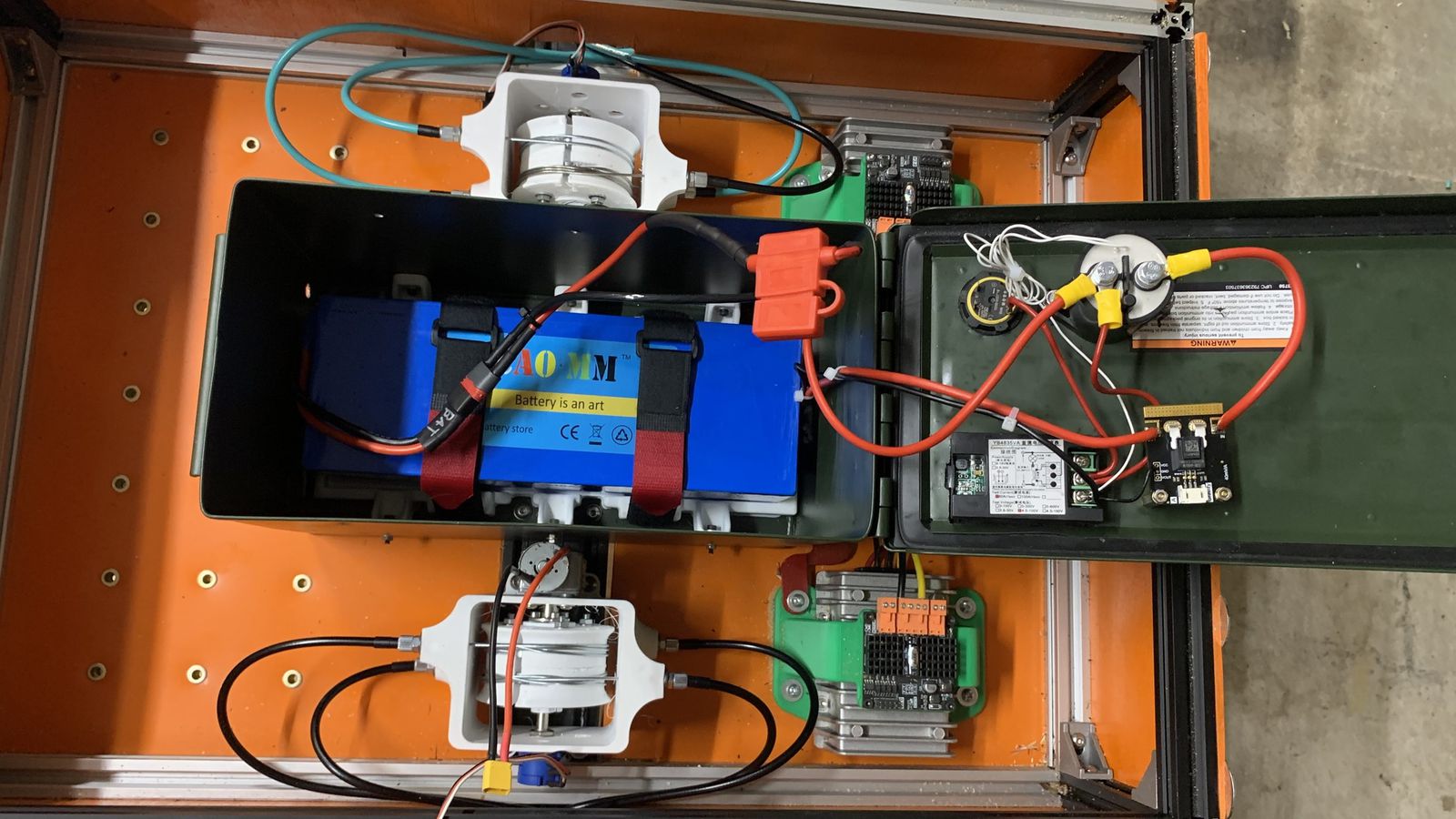
This picture shows more clearly how the rotary actuators worked. They each pulled 4 cables around a capstan to rotate 2 different wheels in opposite directions. I ran into trouble with the cables getting tangled up, friction/binding, play, insufficient torque and speed. Each had a brushed gearmotor and a potentiometer, I controlled them with brushed motor drivers and pot feedback to act like a servo. Although there are 4 steering wheels in this robot, it's a 2 degree of freedom system. Each side is independent of each other, but the front wheel is always the same angle as the rear wheel, just in the opposite direction. Crab walking is not possible here, but that wasn't worth the complexity of adding two more actuators.
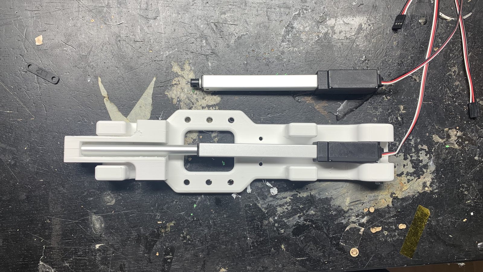
I switched to this linear actuator for simplicity, less play, and higher force on the steering cables.
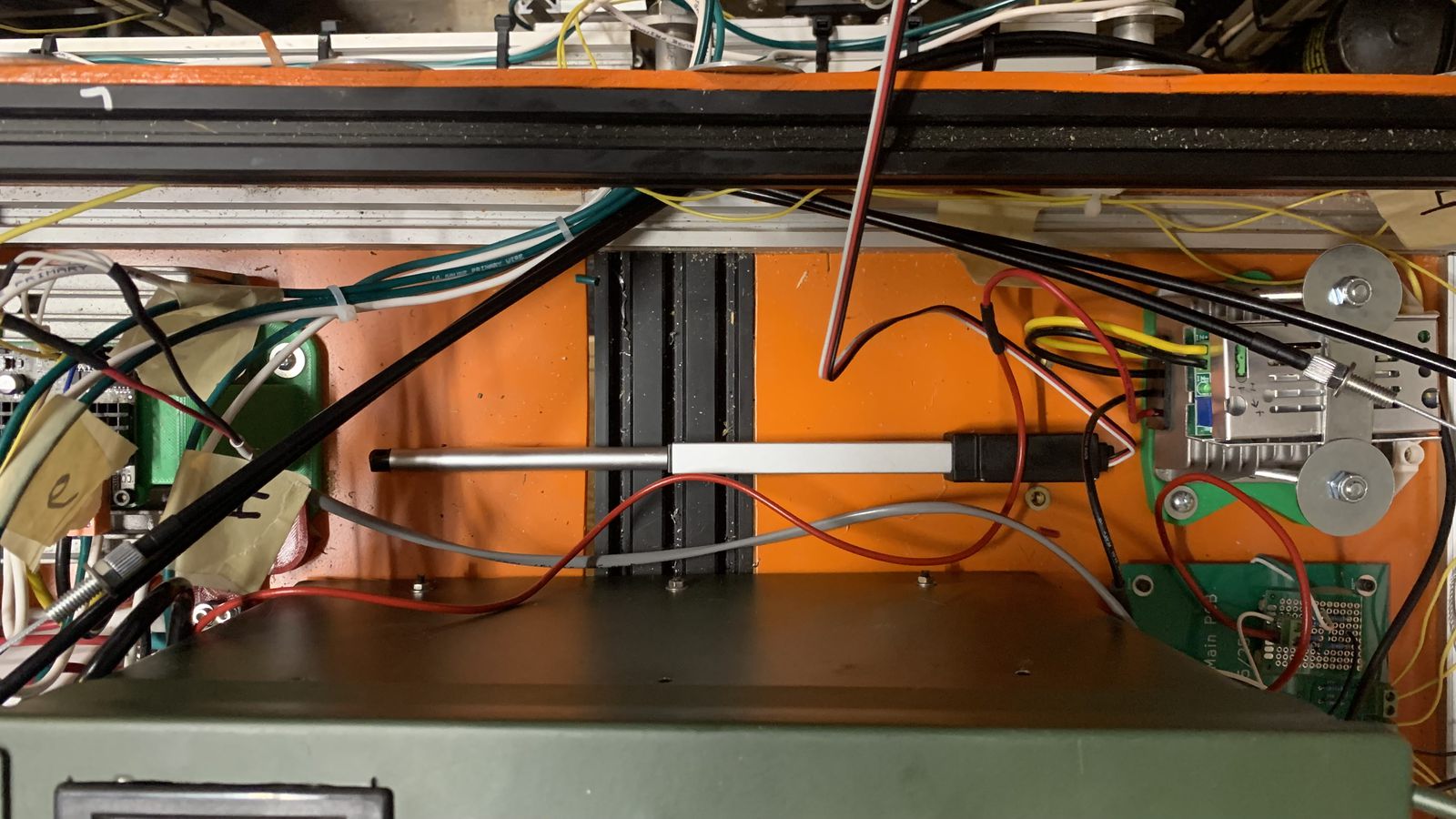
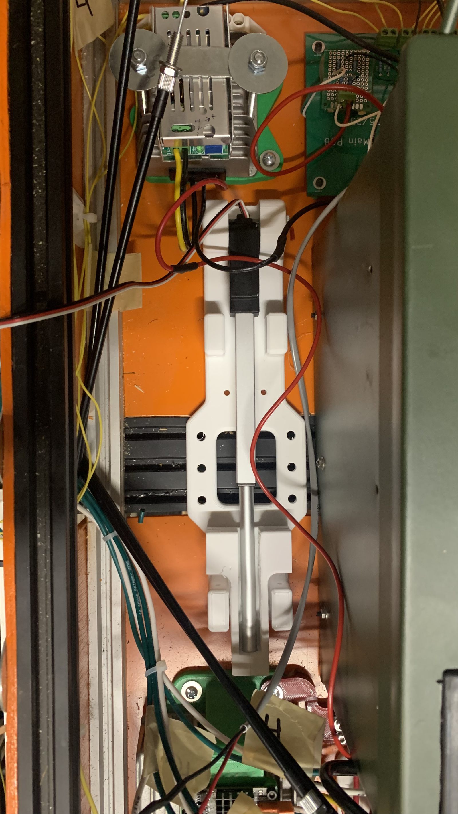
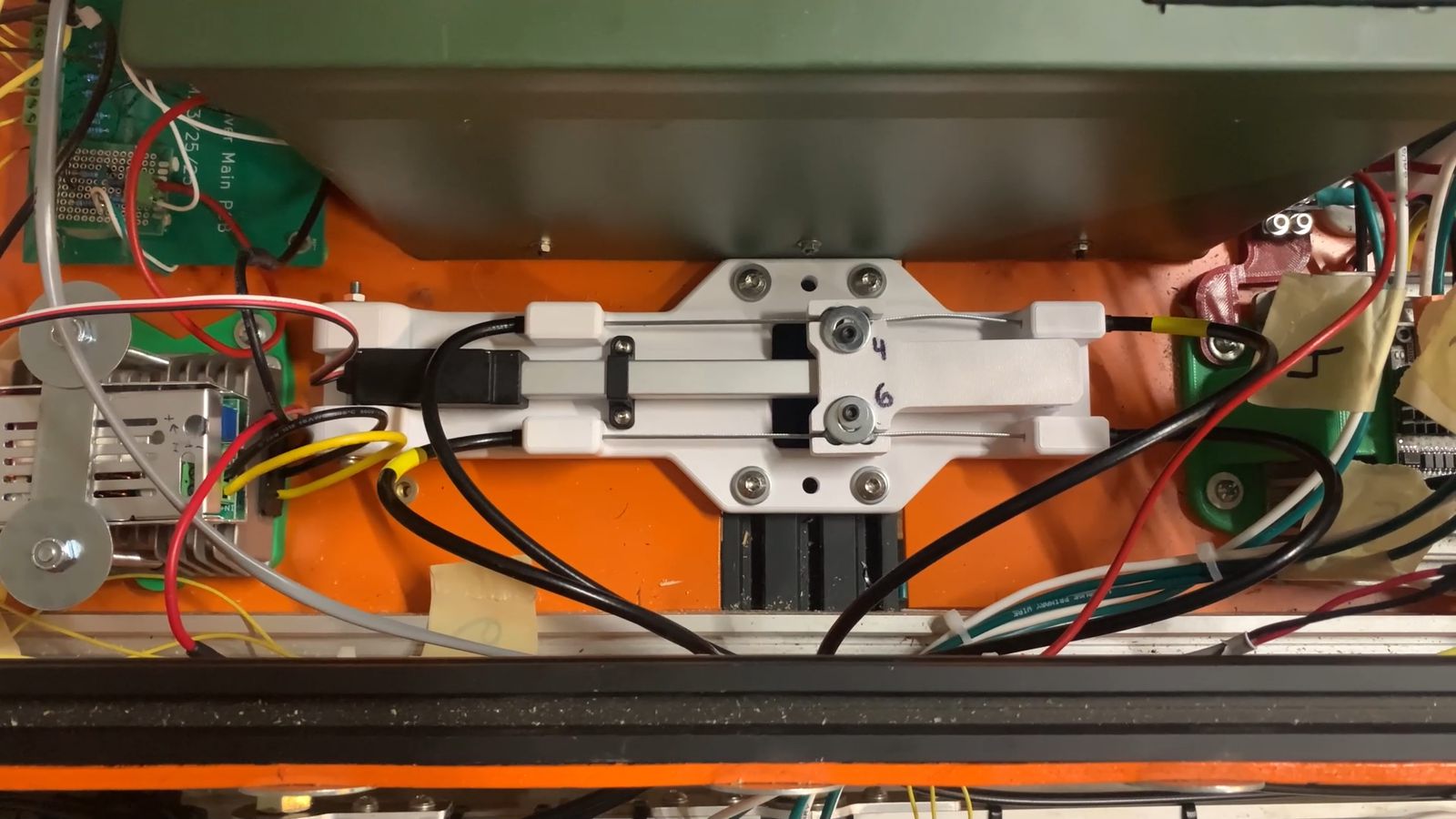
The linear actuator installed. It's a lot more compact and powerful than the rotary one, with less play too.
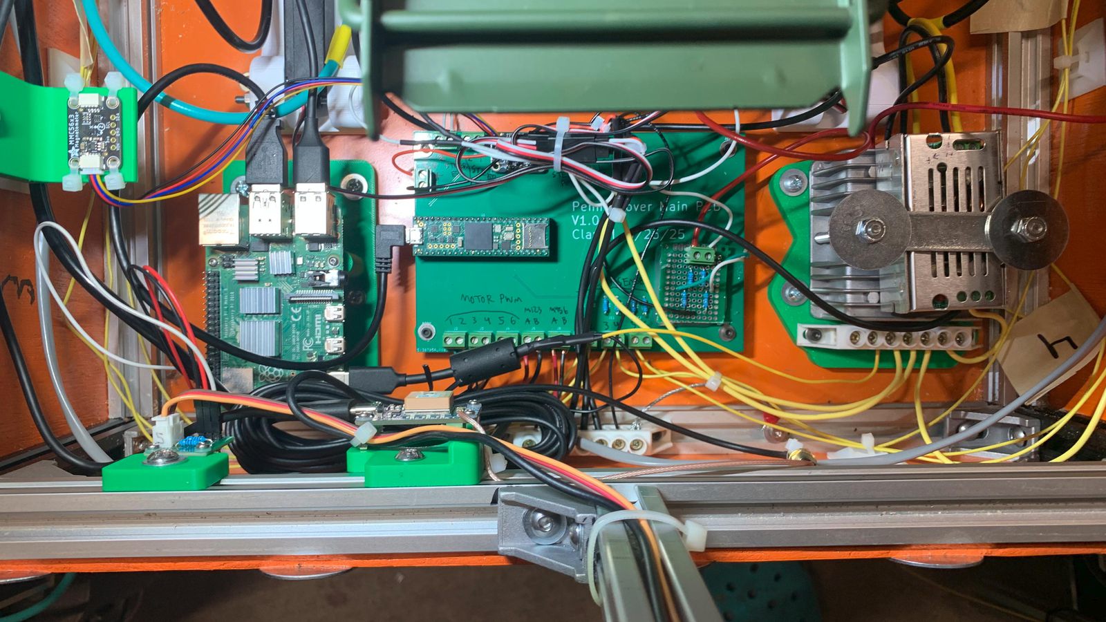
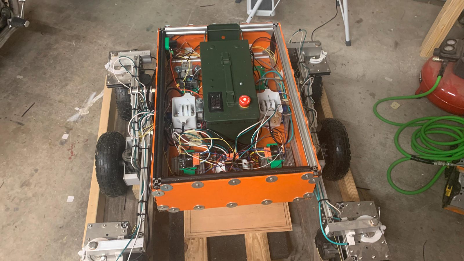
Final integration of all the main control electronics.
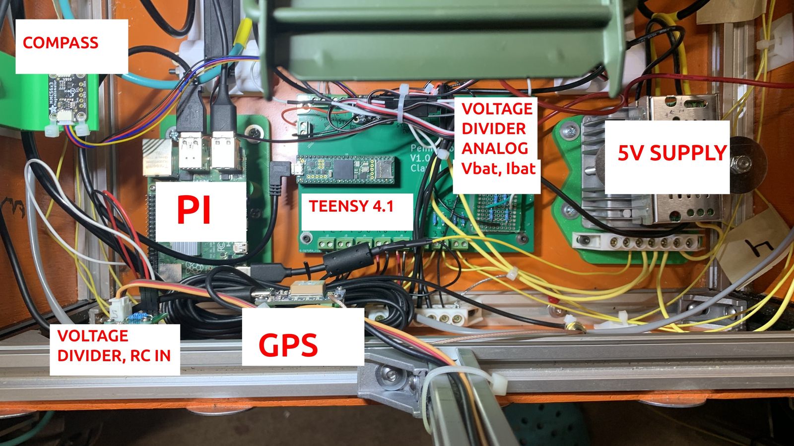
A labeled diagram of the main control electronics.
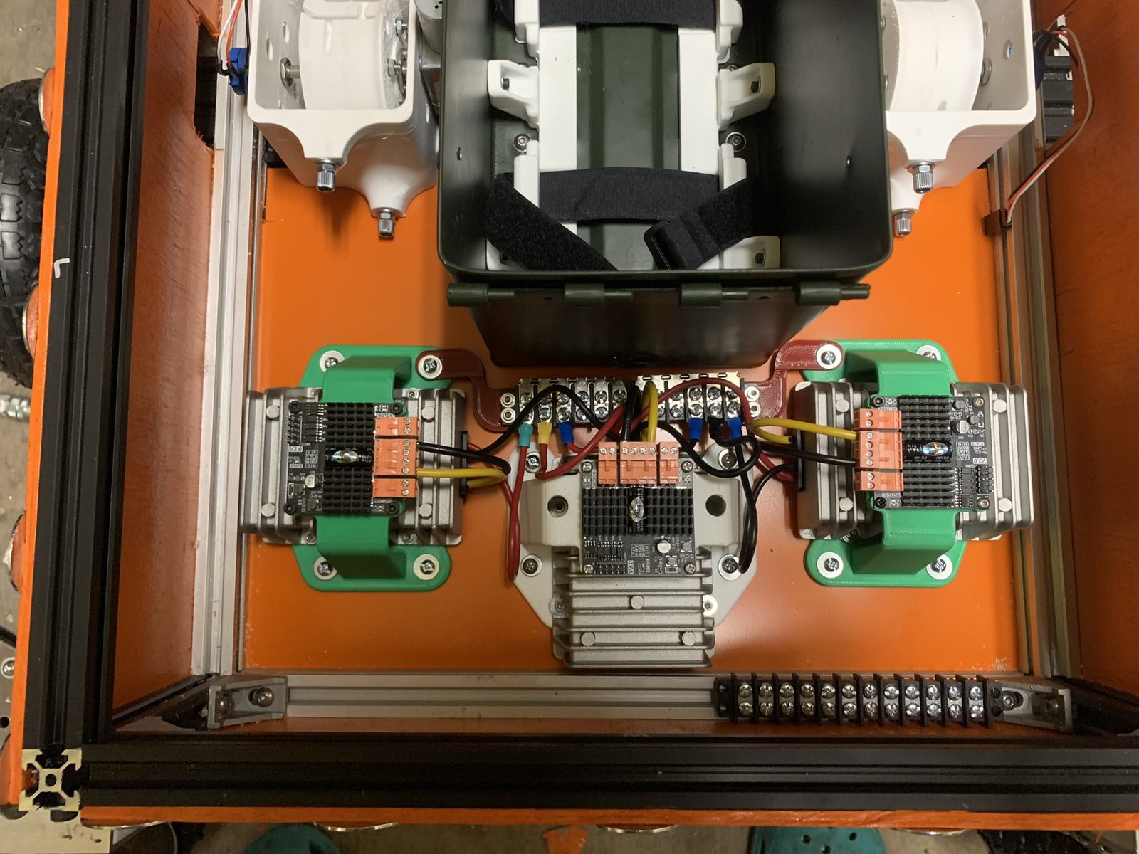
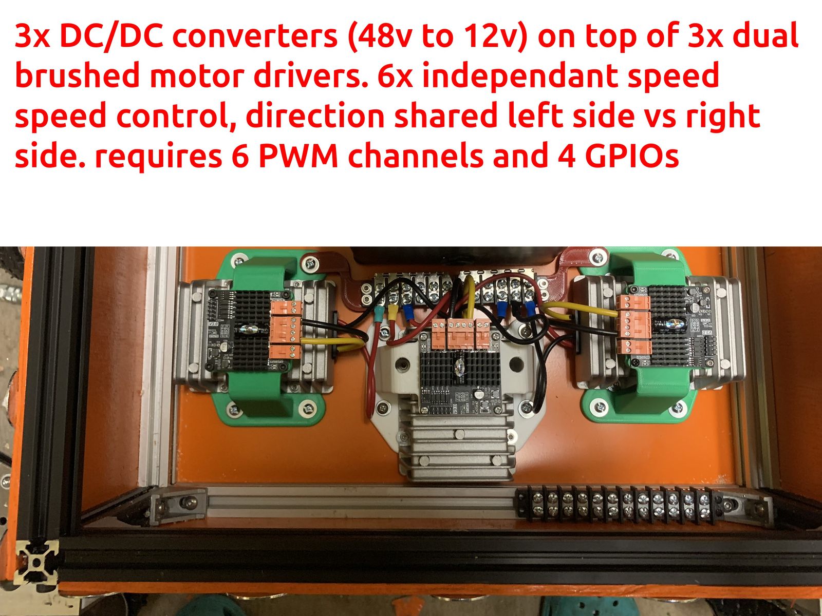
These are the drivers for the 6 drive motors. Each one is dual channel, so it supports 6 total motors with this setup. Each wheel has an independent speed control loop which operates the PWM channel separately. All 3 wheels on each side share the same signal from the microcontroller for direction/enable. This minimizes the number of pins needed from the microcontroller, it just means I can't move two wheels on the same side in different directions at the same time.
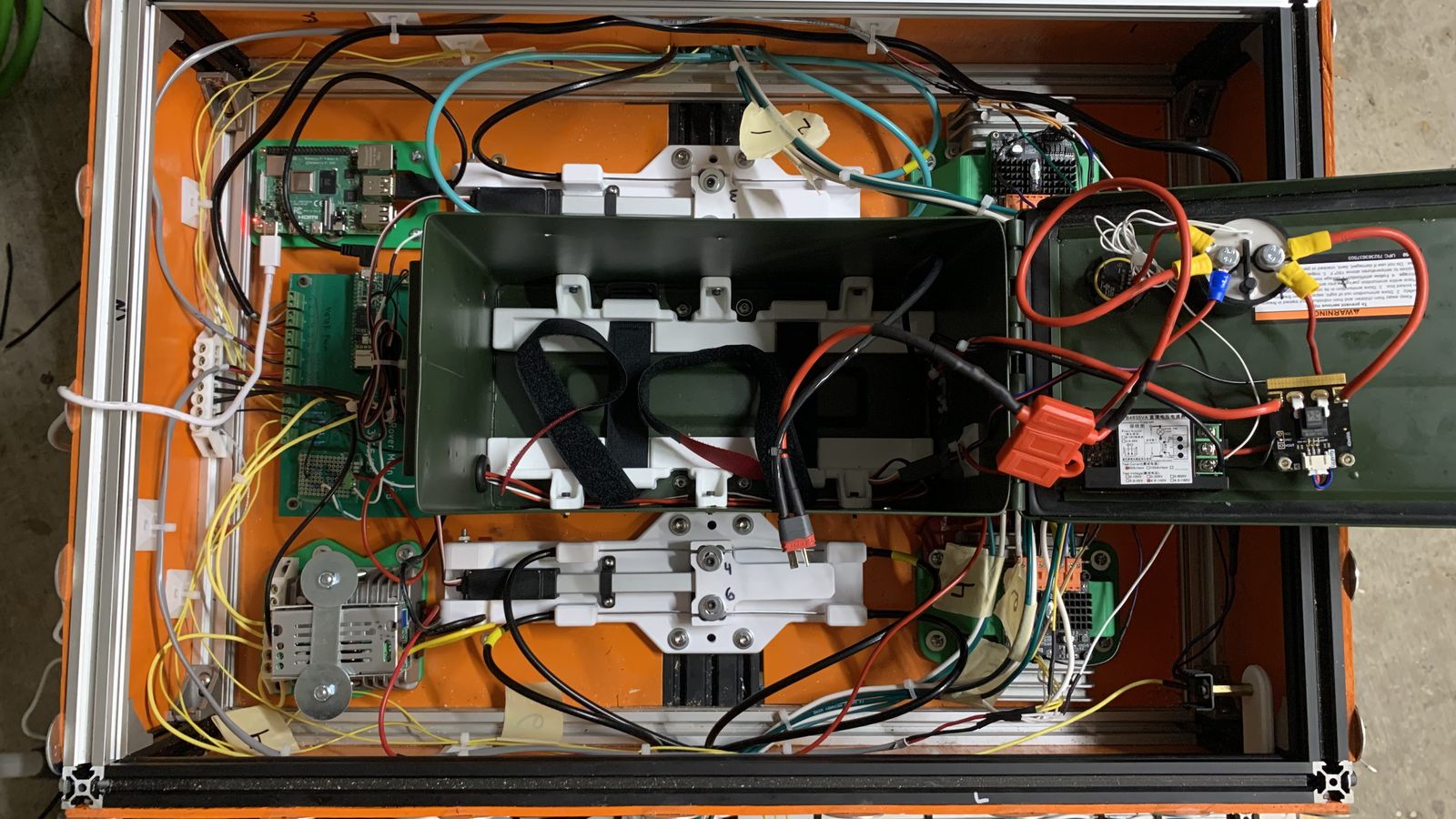
An almost complete overview of all the electronics and the inside of the battery tray. Just missing a few sensor hookups here.
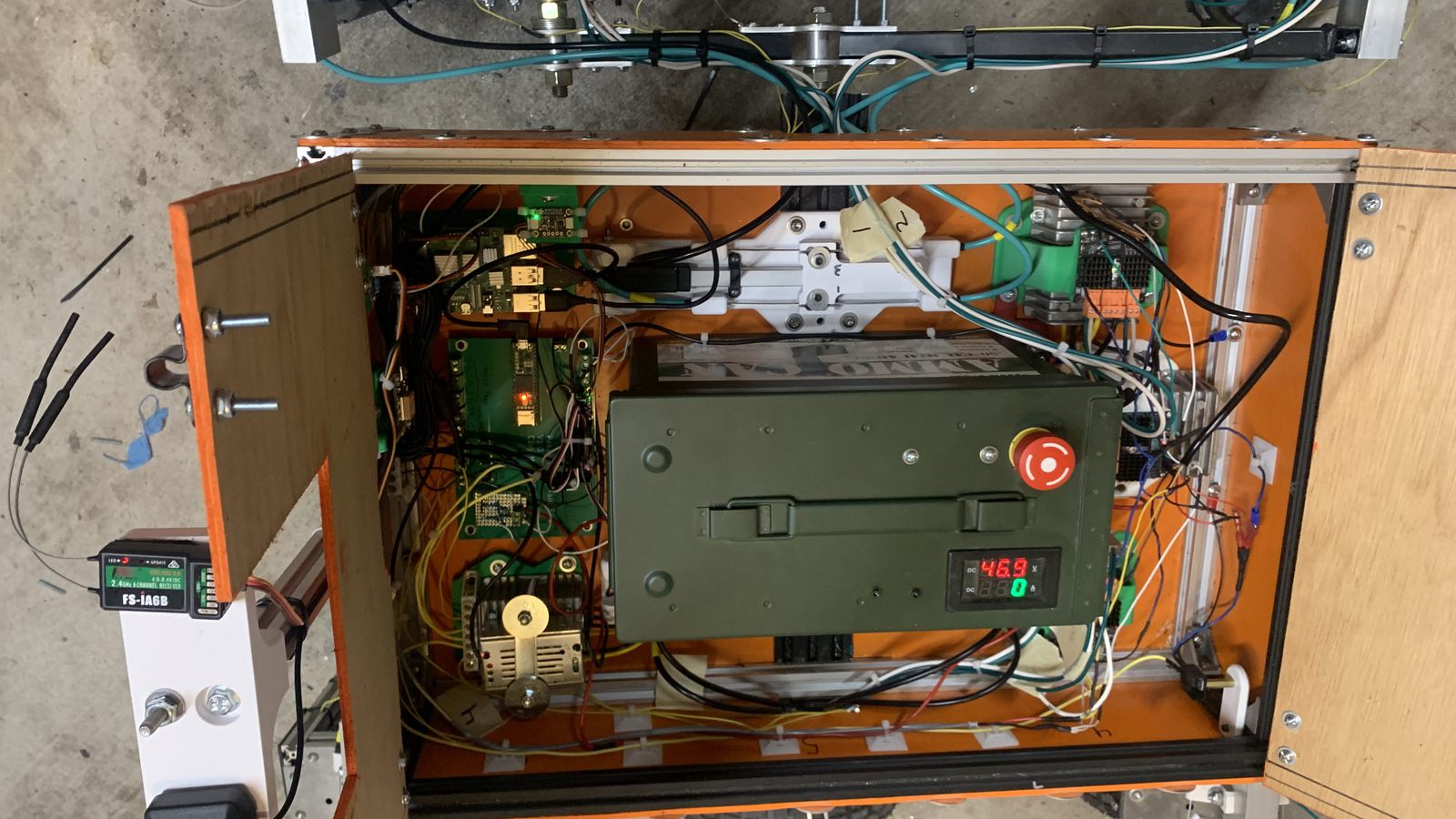
a complete overview of all the finished electronics.
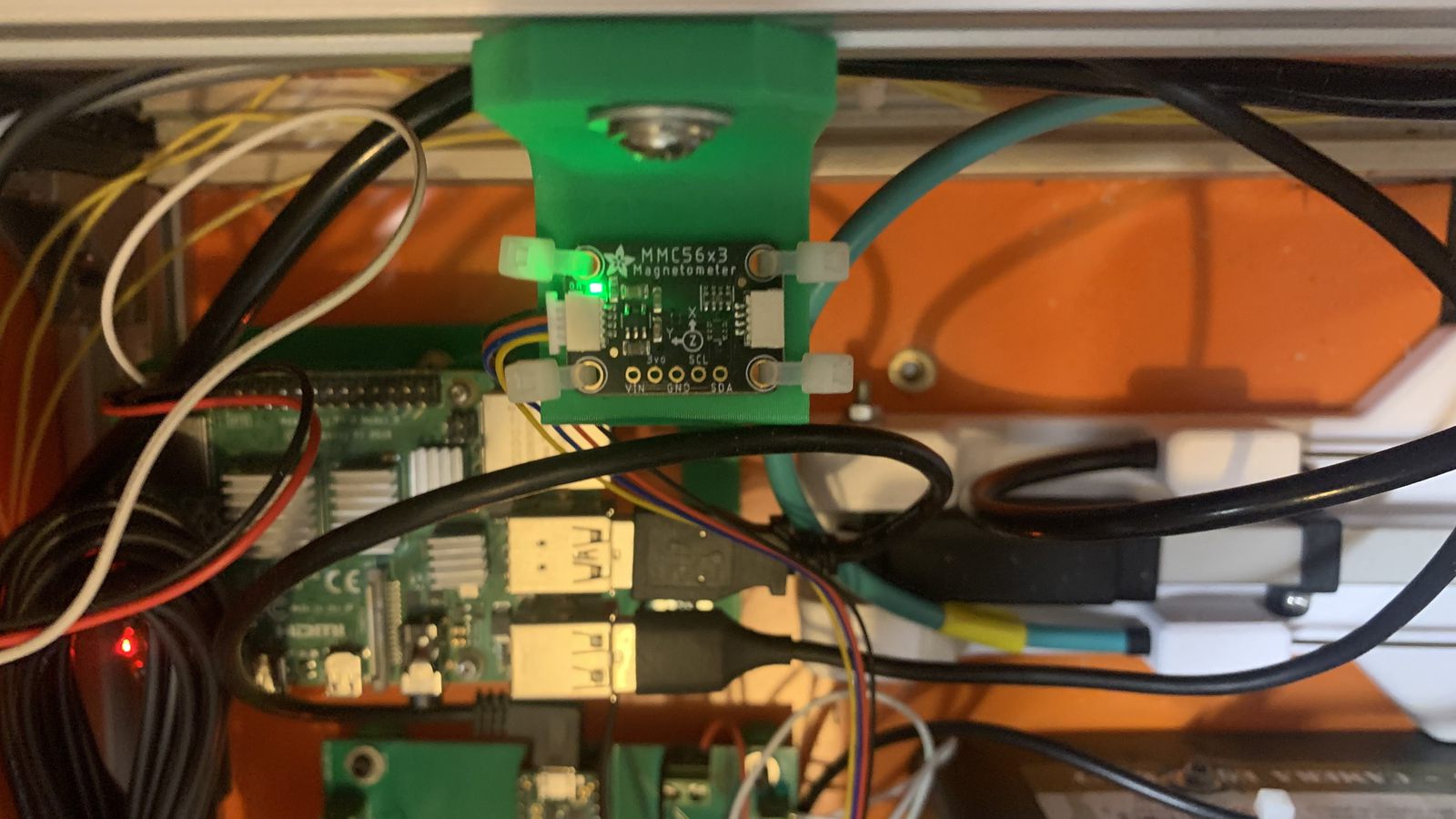
The compass is installed up in a corner above the Pi and Teensy to minimize I2C wire length, and to maximize its distance away from any power electronics, switching, or high current cables. I did a desktop calibration outside the vehicle rotating it about all axes, then just a one axis flat calibration inside the vehicle because I can't easily turn the whole thing upside down. Haven't had any issues.
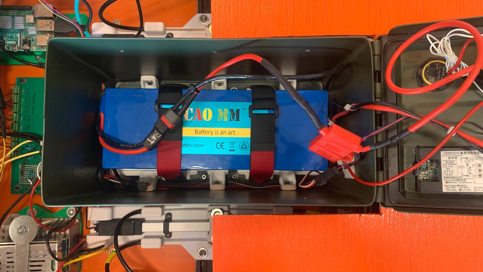
The final battery installation in its fire resistant container with tie downs, fuse, current/voltage sensing, switch, contactor, display.
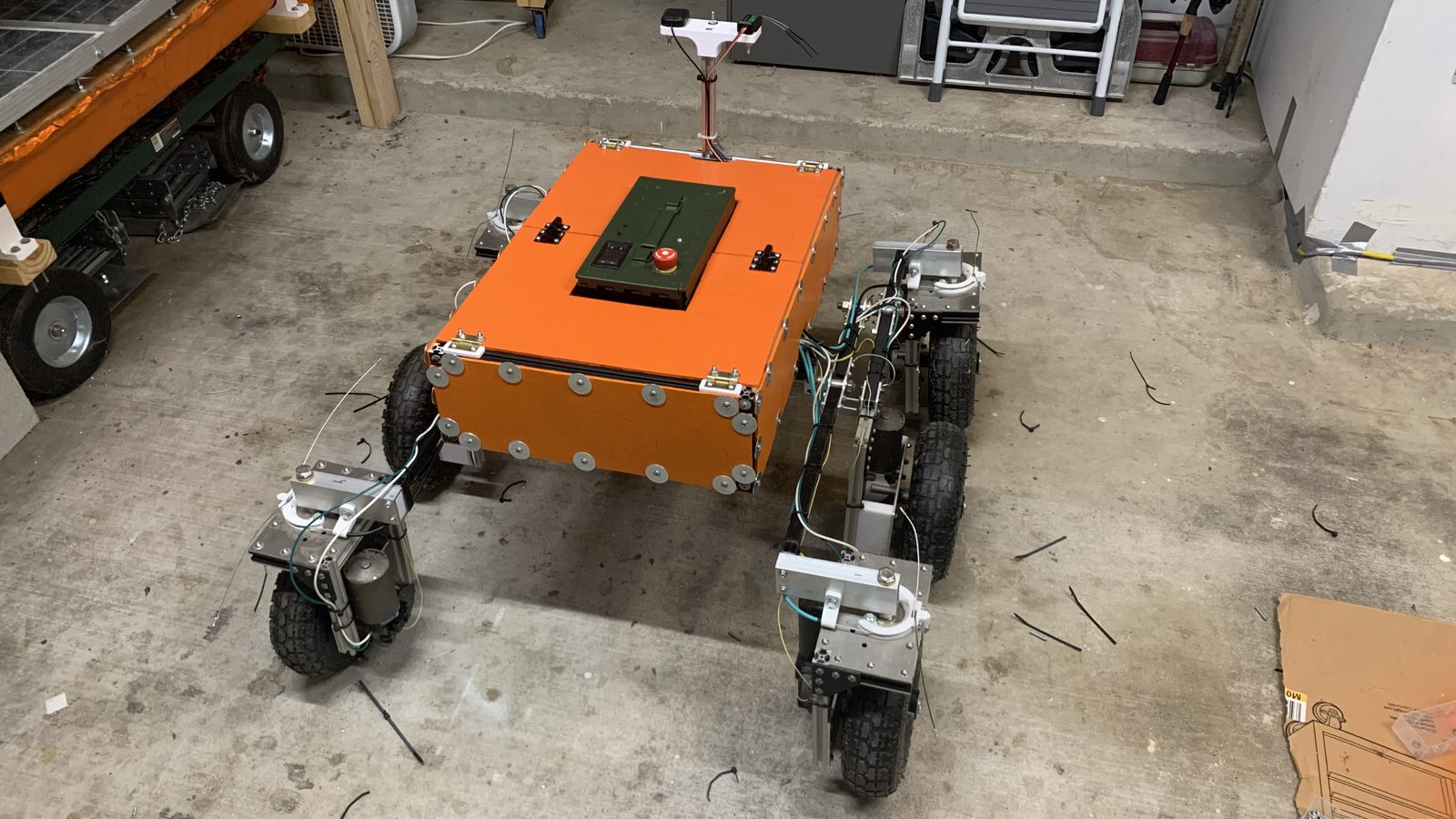
The fully assembled vehicle, ready for her first outdoor test.
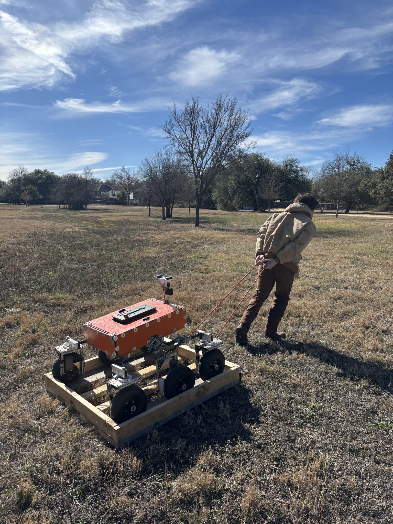
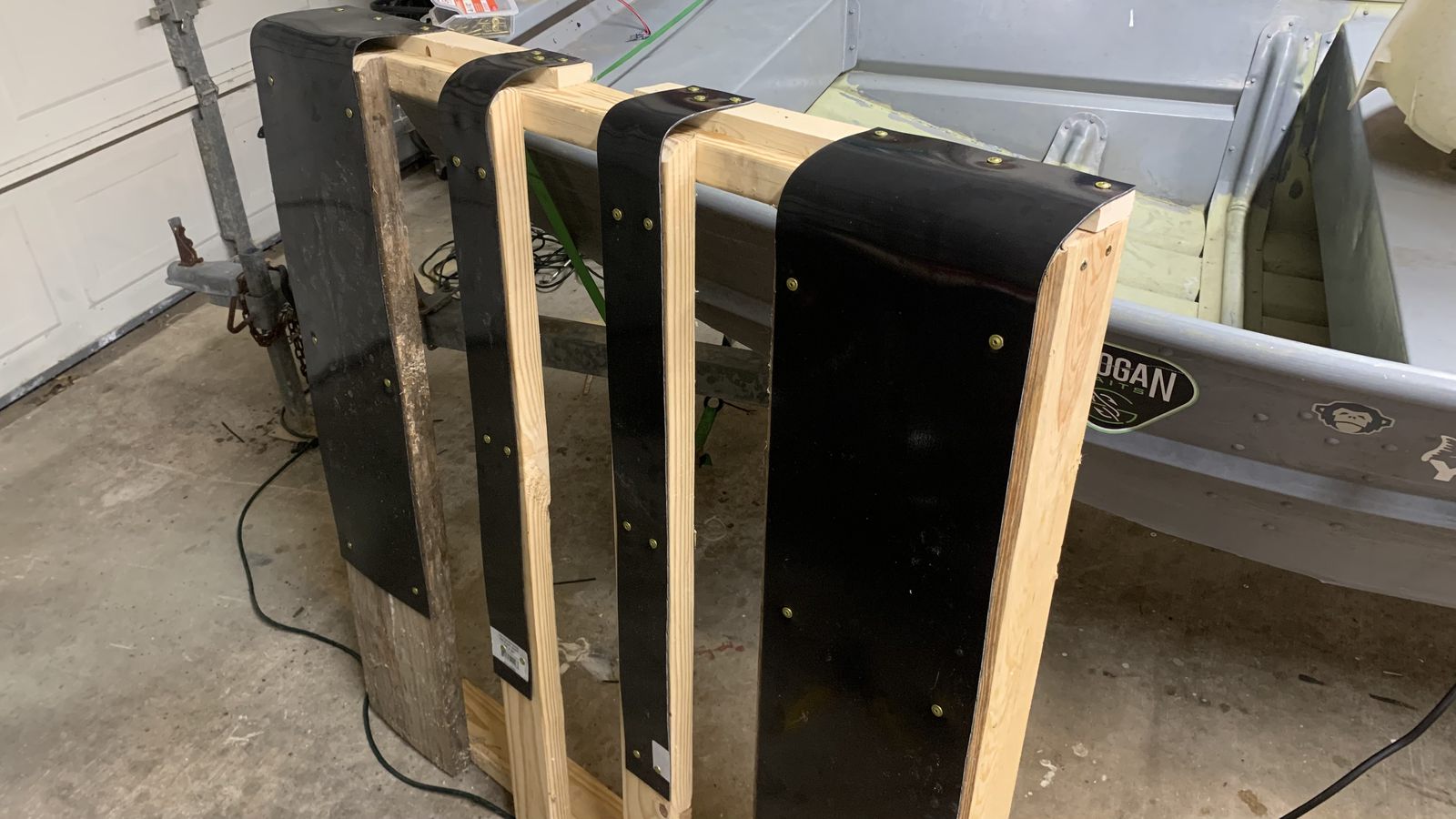
I built this sled ahead of time, made out of the old transportation pallet with some smooth plastic skids underneath. Always gotta have a recovery plan if you're taking an experimental robot that's too big to carry into the field.
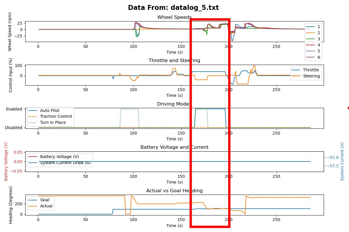
This is basically how the autopilot works. This section of data shows the robot responding to a sudden steering step input. Auto pilot was enabled, a large difference between goal and actual heading was measured, the PID output for steering increased to one side, the turn in place mode was activated because the heading was so far off, the left wheels speed up forward and the right wheels speed up backward. Then, as actual vs goal heading converged, turn in place mode was disabled and the vehicle proceeded with all 6 wheels moving forward.
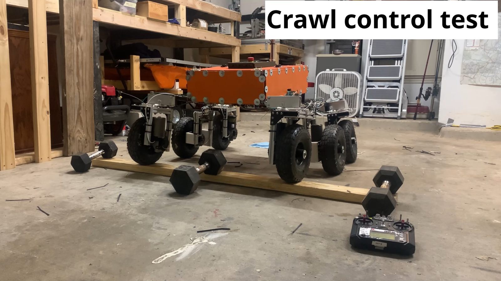
This is an indoor test of the crawl control system. The 2x4 on the ground is an obstacle that stops the vehicle if the motors are operating at very low duty cycle.
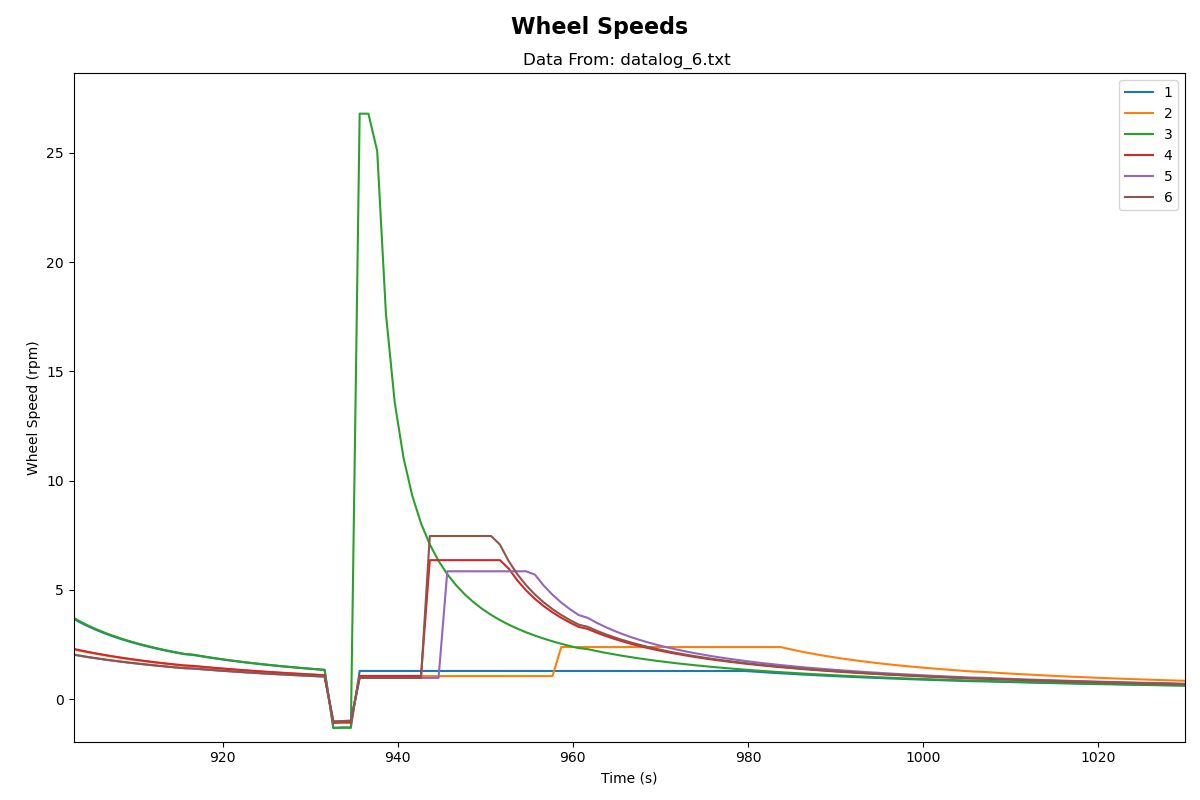
This shows the traction control working. During this segment, the vehicle was slowly crawling until it came to rest against the 2x4 pictured above. The motors running slowly on a low duty cycle had insufficient torque to overcome it, and the wheel speed decreased to 0. The PID control loops on each wheel increased the duty cycle until the vehicle moved over the obstacle, then the speeds quickly shot up. The vehicle settled back into its desired low speed after the obstacle was passed.
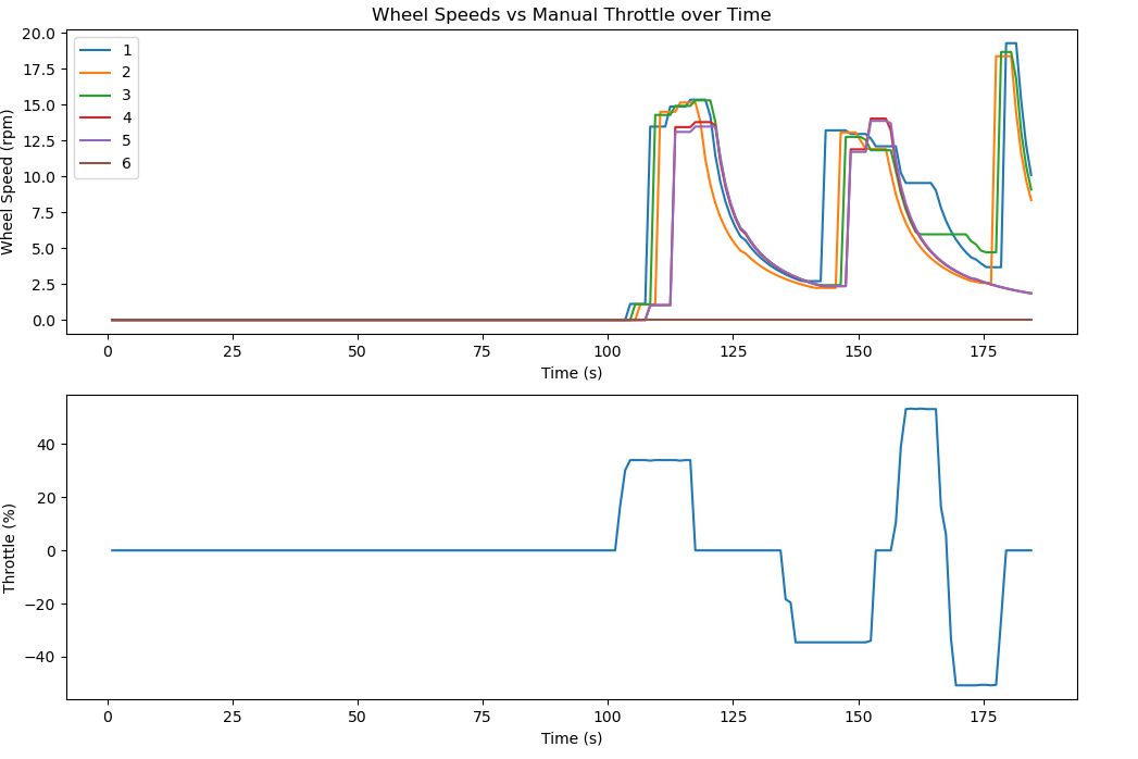
This test data is from manually accelerating via the RC controller. All 6 wheels measure speed independently and update at different times. Speed is measured using a single position switch per wheel that triggers once per rotation. This means sample rate is proportional to wheel speed—at high RPM, updates are frequent; at low RPM, they're sparse. As a result, acceleration appears responsive in the data while deceleration seems delayed, since the system must wait for the next switch trigger to confirm a speed decrease. To address this, the control system tracks elapsed time since the last trigger event. Rather than holding a stale reading indefinitely, it computes the maximum possible RPM given that the switch hasn't fired again yet, and gradually decays the measurement downward toward zero. The reported speed asymptotically approaches zero based on this timeout, with a threshold below which the wheel is assumed to be stopped.
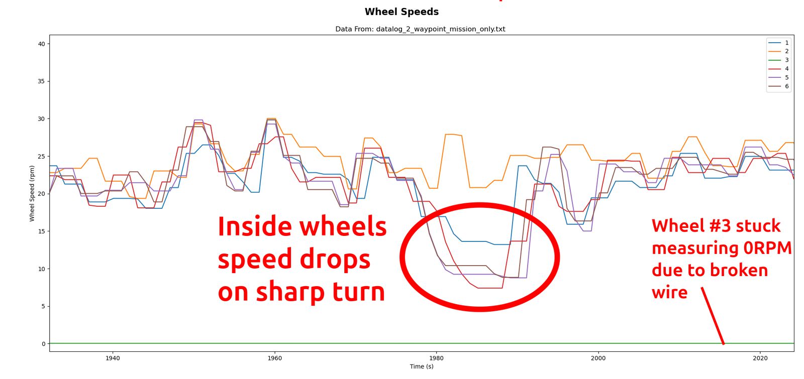
This wheel speed data is from a real outdoor test run. All 6 wheels are being independently controlled via PID loops to stabilize on a different desired speed for each wheel based on turn angle.
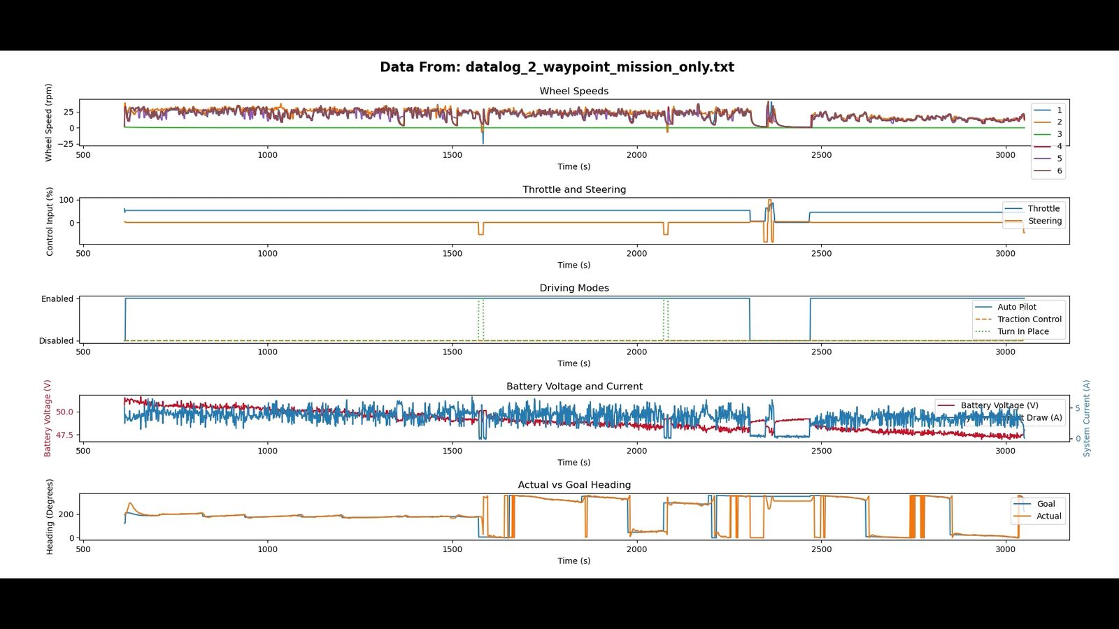
The data it collected during a long autonomous mission
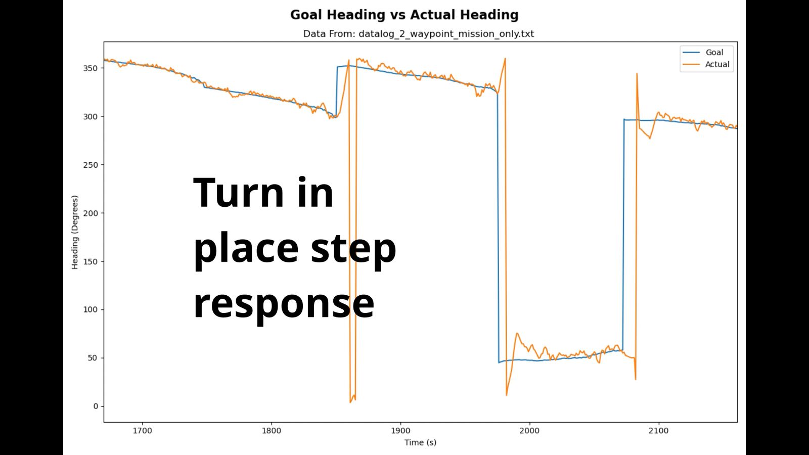
making a tight turn in place maneuver after reaching a waypoint
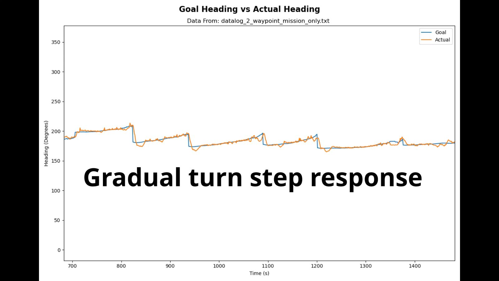
Making gradual turns without turn in place at waypoints that don't drastically change direction